BF-1 Omron, BF-1 Datasheet - Page 35
BF-1
Manufacturer Part Number
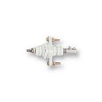
BF-1
Description
ELECTRODE HOLDER
Manufacturer
Omron
Datasheet
1.PFC-N8.pdf
(72 pages)
Specifications of BF-1
Description/function
General and industrial use electrode holder
Equipment Type
Electrode Holder
Lead Free Status / RoHS Status
Lead free / RoHS Compliant
Lead Free Status / RoHS Status
Lead free / RoHS Compliant


61F-APN2
Connect the output terminal Ta of the 61F-Gj to input terminal 2 of the 61F-APN2.
Connection
Connect the contactor coil terminal A to the switching contact terminals 3 and 4 of the 61F-APN2.
Operation of the two pumps can be displayed using the switching contact terminals 5 and 6 of the 61F-APN2.
Timing Chart of Water Supply Alternate Operation
When the 61F-APN2 Alternate Operation Relay is used in combina-
tion with a 61F Controller, the output contacts of the Alternate
Operation Relay will not be switched (OFF) while the contactor is
being excited, and the contactor will not be excited (ON) at the mo-
ment when the output contacts are switched. That is, loads such as
contactors will not be directly turned ON or OFF by the actions of the
output contacts of the 61F-APN2 Alternate Operation Relay.
Instead, they will be turned ON or OFF by the actions of the 61F
Controller.
61F-APN2
Output contact between
1 and 4 and 5 and 8
Output contact between
1 and 3 and 6 and 8
Power supply voltage
between 2 and 7
Power
Output
1-3
Output
1-4
Contact 1
Contact 2
61F
40 ms min.
Ta
Tb
200 ms min.
In case of water supply operation, the output contacts of the Alter-
nate Operation Relay will be switched after the normally closed con-
tacts of the 61F turn OFF upon reaching the control level, and the
output contacts will be already switched when the normally closed
contacts of the 61F turn OFF next time.
Therefore, only the continuous line current needs to be considered
as the load capacity of the 61F-APN2 and the current can be applied
up to the rated line current of 3 A.
61F-APN2
Related parts for BF-1
Image
Part Number
Description
Manufacturer
Datasheet
Request
R

Part Number:
Description:
G6S-2GLow Signal Relay
Manufacturer:
Omron Corporation
Datasheet:
Part Number:
Description:
Compact, Low-cost, SSR Switching 5 to 20 A
Manufacturer:
Omron Corporation
Datasheet:
Part Number:
Description:
Manufacturer:
Omron Corporation
Datasheet:
Part Number:
Description:
Manufacturer:
Omron Corporation
Datasheet:
Part Number:
Description:
Manufacturer:
Omron Corporation
Datasheet:
Part Number:
Description:
Manufacturer:
Omron Corporation
Datasheet:
Part Number:
Description:
Manufacturer:
Omron Corporation
Datasheet:
Part Number:
Description:
Manufacturer:
Omron Corporation
Datasheet: