E8CC-B10C Omron, E8CC-B10C Datasheet - Page 8
E8CC-B10C
Manufacturer Part Number
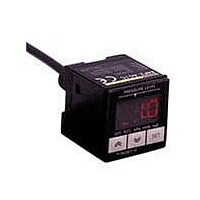
E8CC-B10C
Description
PRESSURE SENSOR:0to980kPa,wLCD
Manufacturer
Omron
Series
E8CCr
Specifications of E8CC-B10C
Pressure Type
Gauge
Operating Pressure
142.14 PSI, 980 kPa
Port Size
Male, 1/8" (3.175mm) 27 NPT
Output
Digital
Voltage - Supply
12 V ~ 24 V
Termination Style
Cable
Operating Temperature
-10°C ~ 55°C
Package / Case
Module
Mounting Style
DIN Rail
Maximum Operating Temperature
+ 55 C
Minimum Operating Temperature
- 10 C
Operating Supply Voltage
15 V, 18 V
Output Voltage
1 V to 5 V
Lead Free Status / RoHS Status
Lead free / RoHS Compliant
Lead Free Status / RoHS Status
Lead free / RoHS Compliant
Other names
E8CCB10C


Output Impedance
1. Measuring the Output Impedance of Voltage Output
Figure 1
Ro : Output impedance
Rx : Load resistance
Eo : Output voltage (terminals open)
Ex : Output voltage (with load Zx connected)
Ix : Load current (with load Zx connected)
In Figure 1, the current (Ix) that flows when the load resistance (Rx)
is connected is calculated as follows:
The output impedance (Ro) in Equation (1) is calculated as follows:
The voltage (Eo) is measured when the output is open, followed by
the voltage (Ex) when a load resistance (for example, the minimum
value of the permitted load resistance of a transducer) is connected.
The measured values Eo and Ex and the connected load resistance
(Rx) are inserted into Equation 2 to calculate the output impedance
(Ro) of the transducer.
2. Measuring the Output Impedance of Current Output
In Figure 2, the voltage (Ex) of the output terminals when the load
resistance (Rx) is connected is calculated as follows:
The output impedance in Equation (3) is calculated as follows:
Eo
Ex = IxRx = (Io − Ix) Ro ......(3)
Ix =
Ro = Rx
Ro = Rx
Models
Models
Ex
Rx
Converter
(
(
Eo - Ex
=
Ro
Eo − Ex
Eo − Ex
Io − Ix
Ex
R0
Ix
http://www.ia.omron.com/
)
)
......(1)
......(2)
......(4)
Ix
Ex
Rx
Pressure Sensors Technical Guide
Here, the current (Io) is measured with the output short-circuited.
Figure 2
Ro : Output impedance
Rx : Load resistance
Io : Output current (output terminal short-circuited)
Ix : Output current (with load Rx connected)
Ex : Output voltage (with load Rx connected)
Next, the output current (Ix) is measured when a load resistance (for
example, the maximum value of the permitted load resistance of a
transducer) is connected. The measured values Io and Ix and the
value of the connected load resistance (Rx) are inserted into Equation
4, and the output impedance (Ro) of the transducer is calculated. The
output impedance of the transducer introduced here is the value for
normal operation.
3. Desirable Output Impedance
In general, it is best to make the output impedance of a voltage output
transducer as small as possible, i.e., as close to 0 W as possible, to
minimize the effects of load fluctuations on the transducer.
For a current output transducer, the opposite is true: the higher the
impedance (the closer to infinite impedance), the better.
4. Example of Calculation Using Impedance
Analog Voltage
Output Sensor
Error in analog
voltage output
Ro = 100Ω
Io
Rx
1kΩ
10Ω
(c)Copyright OMRON Corporation 2008 All Rights Reserved.
Transducer
Ro
Io - lx
=
(
Approximately 10%
Approximately 1%
1 −
Rx =1 kΩ or higher
Error
Ix
Ex
Ro + Rx
Rx
Load
Rx
)
× 100%
8
Related parts for E8CC-B10C
Image
Part Number
Description
Manufacturer
Datasheet
Request
R

Part Number:
Description:
SENSOR PRESSURE 1-5V 0-98KPA NPN
Manufacturer:
Omron
Datasheet:

Part Number:
Description:
PRESSURE SENSOR
Manufacturer:
Omron
Datasheet:

Part Number:
Description:
G6S-2GLow Signal Relay
Manufacturer:
Omron Corporation
Datasheet:
Part Number:
Description:
Compact, Low-cost, SSR Switching 5 to 20 A
Manufacturer:
Omron Corporation
Datasheet:
Part Number:
Description:
Manufacturer:
Omron Corporation
Datasheet:
Part Number:
Description:
Manufacturer:
Omron Corporation
Datasheet:
Part Number:
Description:
Manufacturer:
Omron Corporation
Datasheet:
Part Number:
Description:
Manufacturer:
Omron Corporation
Datasheet:
Part Number:
Description:
Manufacturer:
Omron Corporation
Datasheet:
Part Number:
Description:
Manufacturer:
Omron Corporation
Datasheet: