SD400R20PC Vishay, SD400R20PC Datasheet - Page 5
SD400R20PC
Manufacturer Part Number
SD400R20PC
Description
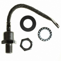
DIODE STD REC 2000V 400A DO-9
Manufacturer
Vishay
Specifications of SD400R20PC
Voltage - Forward (vf) (max) @ If
1.62V @ 1500A
Voltage - Dc Reverse (vr) (max)
2000V (2kV)
Current - Average Rectified (io)
400A
Current - Reverse Leakage @ Vr
15mA @ 2000V
Diode Type
Standard
Speed
Standard Recovery >500ns, > 200mA (Io)
Mounting Type
Chassis, Stud Mount
Package / Case
DO-205AB, DO-9, Stud
Product
Standard Recovery Rectifier
Configuration
Single
Reverse Voltage
2000 V
Forward Voltage Drop
1.62 V at 1500 A
Forward Continuous Current
480 A
Max Surge Current
8640 A
Reverse Current Ir
15000 uA
Mounting Style
Stud
Maximum Operating Temperature
+ 190 C
Minimum Operating Temperature
- 40 C
Lead Free Status / RoHS Status
Lead free / RoHS Compliant
Reverse Recovery Time (trr)
-
Capacitance @ Vr, F
-
Lead Free Status / RoHS Status
Lead free / RoHS Compliant, Lead free / RoHS Compliant
Other names
*SD400R20PC
VS-SD400R20PC
VS-SD400R20PC
VSSD400R20PC
VSSD400R20PC
VS-SD400R20PC
VS-SD400R20PC
VSSD400R20PC
VSSD400R20PC


www.irf.com
Number Of Equal Amplitude Half Cycle Current Pulses (N)
8000
7000
6000
5000
4000
3000
2000
Fig. 5 - Maximum Non-Repetitive Surge Current
1
At Any R ated Load Condition And With
S D400N/ R S eries
R ated V
550
500
450
400
350
300
250
200
150
100
800
700
600
500
400
300
200
100
50
0
0
0
0
R R M
RMS Limit
50 100 150 200 250 300 350 400
100 200 300 400 500 600 700
Applied Following S urge.
Average Forward Current (A)
Average Forward Current (A)
180°
120°
DC
90°
60°
30°
180°
120°
10
90°
60°
30°
@ 60 Hz 0.0083 s
@ 50 Hz 0.0100 s
Initial T = 190°C
Fig. 3 - Forward Power Loss Characteristics
Fig. 4 - Forward Power Loss Characteristics
J
Conduction Angle
S D400N/ R S eries
T = 190°C
Conduction Period
J
S D400N/ R S eries
T = 190°C
J
100
RMS Limit
10 30 50 70 90 110 130 150 170 190
10 30 50 70 90 110 130 150 170 190
Maximum Allowable Ambient T emperature (°C)
Maximum Allowable Ambient T emperature (°C)
9000
8000
7000
6000
5000
4000
3000
2000
1000
Fig. 6 - Maximum Non-Repetitive Surge Current
0.01
Maximum Non R epetitive S urge Current
S D400N/ R S eries
Pulse T rain Duration (s)
Bulletin I2082 rev. D 03/03
Versus Pulse T rain Duration.
SD400N/R Series
No Voltage R eapplied
R ated V
0.1
Initial T = 190°C
RRM
R eapplied
J
5
1
Related parts for SD400R20PC
Image
Part Number
Description
Manufacturer
Datasheet
Request
R

Part Number:
Description:
General Purpose Silicon Switching Rectifier
Manufacturer:
Punjab Wireless Systems Ltd.
Part Number:
Description:
SD40 distribution box, L-left profile M12-A sockets, built-in control cable
Manufacturer:
SHIELD [SHIELD s.r.l.]
Datasheet:

Part Number:
Description:
357-036-542-201 CARDEDGE 36POS DL .156 BLK LOPRO
Manufacturer:
Vishay
Datasheet:
Part Number:
Description:
357-036-542-201 CARDEDGE 36POS DL .156 BLK LOPRO
Manufacturer:
Vishay
Datasheet:
Part Number:
Description:
357-036-542-201 CARDEDGE 36POS DL .156 BLK LOPRO
Manufacturer:
Vishay
Datasheet:
Part Number:
Description:
357-036-542-201 CARDEDGE 36POS DL .156 BLK LOPRO
Manufacturer:
Vishay
Datasheet:
Part Number:
Description:
357-036-542-201 CARDEDGE 36POS DL .156 BLK LOPRO
Manufacturer:
Vishay
Datasheet:
Part Number:
Description:
357-036-542-201 CARDEDGE 36POS DL .156 BLK LOPRO
Manufacturer:
Vishay
Datasheet:
Part Number:
Description:
357-036-542-201 CARDEDGE 36POS DL .156 BLK LOPRO
Manufacturer:
Vishay
Datasheet:
Part Number:
Description:
357-036-542-201 CARDEDGE 36POS DL .156 BLK LOPRO
Manufacturer:
Vishay
Datasheet:
Part Number:
Description:
357-036-542-201 CARDEDGE 36POS DL .156 BLK LOPRO
Manufacturer:
Vishay
Datasheet:
Part Number:
Description:
357-036-542-201 CARDEDGE 36POS DL .156 BLK LOPRO
Manufacturer:
Vishay
Datasheet:
Part Number:
Description:
357-036-542-201 CARDEDGE 36POS DL .156 BLK LOPRO
Manufacturer:
Vishay
Datasheet:
Part Number:
Description:
357-036-542-201 CARDEDGE 36POS DL .156 BLK LOPRO
Manufacturer:
Vishay
Datasheet:
Part Number:
Description:
357-036-542-201 CARDEDGE 36POS DL .156 BLK LOPRO
Manufacturer:
Vishay
Datasheet: