G6K-2G-Y-DC5 Omron, G6K-2G-Y-DC5 Datasheet - Page 8
G6K-2G-Y-DC5
Manufacturer Part Number
G6K-2G-Y-DC5
Description
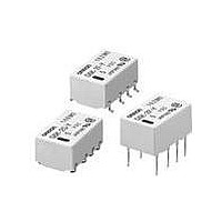
SMT RELAY
Manufacturer
Omron
Series
G6K2r
Datasheet
1.G6K-2F-TR_DC24.pdf
(12 pages)
Specifications of G6K-2G-Y-DC5
Contact Form
2 Form C
Coil Voltage
5 VDC
Coil Current
21.1 mA
Coil Type
Non-Latching
Power Consumption
100 mW
Termination Style
Solder Pad
Maximum Switching Current
1 A
Contact Rating
0.3 A at 125 VAC, 1 A at 30 VDC
Lead Free Status / RoHS Status
Lead free / RoHS Compliant
Lead Free Status / RoHS Status
Lead free / RoHS Compliant
Other names
G6K2GY5DC OMRG6K2GY5DC
Available stocks
Company
Part Number
Manufacturer
Quantity
Price
Company:

Part Number:
G6K-2G-Y-DC5V
Manufacturer:
OMRON
Quantity:
12 000


■ Recommended Soldering Method
Temperature indicates the surface temperature of the PCBs.
IRS Method (for surface mounting terminal models)
(1) IRS Method (Mounting Solder: Lead)
• The thickness of cream solder to be applied should be within a range between 150 and 200 μm on OMRON’s recommended PCB pattern.
• In order to perform correct soldering, it is recommended that the correct soldering conditions be maintained as shown below on the left side.
Visually check that the Relay is properly soldered.
Precautions
■ Correct Use
Handling
Do not unpack the relay until mounting it.
Soldering
Solder: JIS Z3282, H63A or equivalent
Soldering temperature: Approx. 250°C (260°C if the DWS method is
used)
Soldering time: Approx. 5 s max. (approx. 2 s for the first time and
approx. 3 s for the second time if the DWS method is used)
Be sure to make a molten solder level adjustment so that the solder
will not overflow on the PCB.
Claw Securing Force During Automatic
Mounting
During automatic insertion of Relays, make sure to set the securing
force of each claw to the following so that the Relays characteristics
will be maintained.
74
PCB
Correct Soldering
220 to
180 to
245
200
150
Terminal
Low Signal Relay
Relay
Solder
Land
Preheating
90 to 120
Direction A: 1.96 N
Direction B: 4.90 N
Direction C: 1.96 N
Incorrect Soldering
Soldering
20 to 30
Insufficient
amount of
solder
G6K
Time (s)
Excessive
amount of
solder
(2) IRS Method (Mounting Solder: Lead-free)
Environmental Conditions During Operation,
Storage, and Transportation
It is best to keep the relay in its packaging in a controlled environ-
ment until it is ready for mounting.
If the Relay is stored for a long time in an adverse environment with
high temperature, high humidity, organic gases, or sulfide gases, sul-
fide or oxide films will form on the contact surfaces. These films may
result in unstable contact, contact problems, or functional problems.
Therefore, operate, store, or transport the product under specified
environmental conditions.
Latching Relay Mounting
Make sure that the vibration or shock that is generated from other
devices, such as relays in operation, on the same panel and imposed
on the Latching Relay does not exceed the rated value, otherwise the
Latching Relay that has been set may be reset or vice versa. The
Latching Relay is reset before shipping. If excessive vibration or
shock is imposed, however, the Latching Relay may be set acciden-
tally. Be sure to apply a reset signal before use.
Maximum Allowable Voltage
The maximum allowable voltage of the coil can be obtained from the
coil temperature increase and the heat-resisting temperature of coil
insulating sheath material. (Exceeding the heat-resisting tempera-
ture may result in burning or short-circuiting.) The maximum allow-
able voltage also involves important restrictions which include the
following:
Note: The temperature profile indicates the
250 max.
230
180
150
temperature of the relay terminal
section.
Upper surface of case (peak):
255˚C max.
120 max.
Preheating
30 max.
Soldering
Relay
terminal
section
Time (s)
Related parts for G6K-2G-Y-DC5
Image
Part Number
Description
Manufacturer
Datasheet
Request
R

Part Number:
Description:
Low Signal Relays - PCB 3.2MM DPDT L 24DC
Manufacturer:
Omron
Datasheet:
Part Number:
Description:
Low Signal Relays - PCB 3.2MM DPDT L 12DC
Manufacturer:
Omron
Datasheet:

Part Number:
Description:
SMT RELAY
Manufacturer:
Omron
Datasheet:

Part Number:
Description:
Manufacturer:
Omron Corporation
Datasheet:


Part Number:
Description:
SMT RELAY
Manufacturer:
Omron
Datasheet:
Part Number:
Description:
SMT RELAY
Manufacturer:
Omron
Datasheet:
Part Number:
Description:
SMT TAPE-N-REEL RELAY
Manufacturer:
Omron
Datasheet:
Part Number:
Description:
SMT TAPE-N-REEL RELAY
Manufacturer:
Omron
Datasheet:
Part Number:
Description:
SMT TAPE-N-REEL RELAY
Manufacturer:
Omron
Datasheet:
Part Number:
Description:
SMT TAPE-N-REEL RELAY
Manufacturer:
Omron
Datasheet:
Part Number:
Description:
SMT TAPE-N-REEL RELAY
Manufacturer:
Omron
Datasheet:
Part Number:
Description:
SMT TAPE-N-REEL RELAY
Manufacturer:
Omron
Datasheet:
Part Number:
Description:
SMT TAPE-N-REEL RELAY
Manufacturer:
Omron
Datasheet: