G6W-1F DC24 Omron, G6W-1F DC24 Datasheet - Page 7
G6W-1F DC24
Manufacturer Part Number
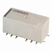
G6W-1F DC24
Description
HF SMT RELAY
Manufacturer
Omron
Series
G6Wr
Datasheet
1.G6W-1F_DC12.pdf
(10 pages)
Specifications of G6W-1F DC24
Relay Type
RF
Circuit
SPDT (1 Form C)
Contact Rating @ Voltage
0.01A @ 30VAC/DC
Coil Type
Standard
Coil Current
8.3mA
Coil Voltage
24VDC
Control On Voltage (max)
19.2 VDC
Control Off Voltage (min)
2.4 VDC
Mounting Type
Surface Mount
Termination Style
Gull Wing
Lead Free Status / RoHS Status
Lead free / RoHS Compliant
Other names
G6W-1F-DC24
G6W1FDC24
Z2046
G6W1FDC24
Z2046


Recommended Soldering Method
■ Temperature Profile According to IRS Method
When performing reflow-soldering, check the profile on an actual device
after setting the temperature condition so that the temperatures at the
relay terminals and the upper surface of the case do not exceed the
limits specified in the following table.
Precautions
■ Correct Use
Handling
Use the Relay as soon as possible after opening the moisture-proof
package. If the Relay is left for a long time after opening the moisture-
proof package, the appearance may suffer and seal failure may occur
after the solder mounting process. To store the Relay after opening the
moisture-proof package, place it into the original package and sealed the
package with adhesive tape.
When washing the product after soldering the Relay to a PCB, use a
water-based solvent or alcohol-based solvent, and keep the solvent tem-
perature to less than 40°C. Do not put the Relay in a cold cleaning bath
immediately after soldering.
Dropping the Relay may cause damage to its functional capability.
Never use the Relay if it is dropped.
Protect the Relays from direct sunlight during operation, storage, and
transportation and keep the relays under normal temperature, humidity,
and pressure.
Coating
Do not use silicone coating to coat the Relay when it is mounted to
the PCB. Do not wash the PCB after the Relay is mounted using
detergent containing silicone. Otherwise, the detergent may remain
on the surface of the Relay.
Measuring
position
Terminal
Upper surface
of case
Item
T4
T3
T2
T1
150°C to 180°C,
120 s max.
---
(T1 to T2, t
Preheating
1
Preheating
)
t
1
230°C min.,
30 s max.
---
Soldering
(T3, t
Soldering
2
t
)
2
Time (s)
250°C max.
255°C max.
Peak value
(T4)
DISCONTINUED
The thickness of cream solder to be applied should be within a range
between 150 and 200 μm on OMRON's recommended PCB pattern.
Visually check that the Relay is properly soldered.
Bottom Ground Soldering Conditions
To solder the bottom ground, manually solder separately from the
terminals according to the following conditions.
• Soldering iron: 50 W
• Iron temperature: 380°C to 400°C
• Soldering time: 10 s max.
Note: The above conditions are for a PCB with OMRON’s recommended
Soldering
Soldering temperature: Approx. 250°C (At 260°C if the DWS method is
used.)
Soldering time: Approx. 5 s max. (approx. 2 s for the first time and
approx. 3 s for the second time if the DWS method is used.)
Be sure to adjust the level of the molten solder so that the solder will not
overflow onto the PCB.
Claw Securing Force During Automatic Insertion
During automatic insertion of Relays, make sure to set the securing force
of the claws to the following values so that the Relay characteristics will
be maintained.
Latching Relay Mounting
Make sure that the vibration or shock that is generated from other
devices, such as relays in operation, on the same panel and imposed on
the Latching Relay does not exceed the rated value, otherwise the Latch-
ing Relay that has been set may be reset or vice versa. The Latching
Relay is reset before shipping. If excessive vibration or shock is imposed,
however, the Latching Relay may be set accidentally. Be sure to apply a
reset signal before use.
PCB
Correct Soldering
Secure the claws to the area indicated by shading.
Do not attach them to the center area or to only part of the
Relay.
patterns and hole perforations. The conditions will depend on the
PCB being used. Therefore, it is recommended to double-check
the suitability under actual PCB conditions.
Terminal
Relay
High-frequency Relay
Solder
Land
Direction A: 4.90 N max.
Direction B: 9.80 N max.
Direction C: 9.80 N max.
A
Incorrect Soldering
C
Insufficient
amount of
solder
B
G6W
Excessive
amount of
solder
333
Related parts for G6W-1F DC24
Image
Part Number
Description
Manufacturer
Datasheet
Request
R

Part Number:
Description:
HF SMT RELAY
Manufacturer:
Omron
Datasheet:

Part Number:
Description:
HF SMT RELAY
Manufacturer:
Omron
Datasheet:
Part Number:
Description:
HF SMT RELAY
Manufacturer:
Omron
Datasheet:
Part Number:
Description:
HF SMT RELAY
Manufacturer:
Omron
Datasheet:
Part Number:
Description:
HF SMT RELAY
Manufacturer:
Omron
Datasheet:
Part Number:
Description:
HF SMT RELAY
Manufacturer:
Omron
Datasheet:
Part Number:
Description:
HF SMT RELAY
Manufacturer:
Omron
Datasheet:

Part Number:
Description:
HF SMT RELAY
Manufacturer:
Omron
Datasheet:
Part Number:
Description:
HF SMT RELAY
Manufacturer:
Omron
Datasheet:
Part Number:
Description:
HF SMT RELAY
Manufacturer:
Omron
Datasheet:
Part Number:
Description:
HF SMT RELAY
Manufacturer:
Omron
Datasheet:
Part Number:
Description:
HF SMT RELAY
Manufacturer:
Omron
Datasheet:

Part Number:
Description:
G6S-2GLow Signal Relay
Manufacturer:
Omron Corporation
Datasheet:
Part Number:
Description:
Compact, Low-cost, SSR Switching 5 to 20 A
Manufacturer:
Omron Corporation
Datasheet: