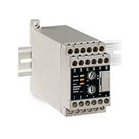
G9SA-EX301 Omron, G9SA-EX301 Datasheet

G9SA-EX301
Specifications of G9SA-EX301
Related parts for G9SA-EX301
G9SA-EX301 Summary of contents
Page 1
... VAC/VDC 2 channels 100 to 240 VAC possible possible VAC/VDC 100 to 240 VAC VAC/VDC 100 to 240 VAC Category Category Part number 4 G9SA-301 G9SA-501 Category Part number Main contacts: 4 G9SA-321-T075 OFF-delay contacts: 3 OFF G9SA-321-T15 G9SA-321-T30 Part number G9SA-EX301 ...
Page 2
... J EXPANSION UNITS WITH OFF-DELAY OUTPUTS The Expansion Unit connects to a G9SA-301, G9SA-501, or G9SA-321. Main contact form Auxiliary contact 3PST-NO SPST-NC Note: The following 15-step OFF-delay time settings are available: T075: 0.5, 1, 1.5, 2, 2.5, 3, 3.5, 4, 4.5, 5, 5.5, 6, 6.5, 7, and 7.5 s T15 10, 11, 12, 13, 14, and 15 s ...
Page 3
... Operating: --25°C to 55°C (with no icing or condensation) Storage: --25°C to 85°C (with no icing or condensation) Operating: 35% to 85% Storage: 35% to 85% 0.98 NSm Approx. 210 g Approx. 270 g EN954-1, EN60204-1, UL508, CSA C22.2 No. 14 EMI: EN55011 group 1 class A EMS: EN50082-2 group 1 4 G9SA-EX301/EX031-Tj Approx. 130 g ...
Page 4
... Application Examples J G9SA-301 (24 VAC/VDC) WITH 2-CHANNEL LIMIT SWITCH INPUT/AUTO-RESET Open Control circuit J G9SA-301 (24 VAC/VDC) WITH 2-CHANNEL LIMIT SWITCH INPUT/MANUAL-RESET Open Control circuit Feedback loop Feedback loop 5 G9SA Timing Chart Limit switches S1 and S2 K1 and K2 (NC) K1 and K2 (NO) KM1 and KM2 (NC) ...
Page 5
... G9SA J G9SA-301 (100 TO 240 VAC) WITH 2-CHANNEL LIMIT SWITCH INPUT/AUTO-RESET Open Control circuit J G9SA-301 (24 VAC/VDC) WITH 2-CHANNEL EMERGENCY STOP SWITCH INPUT/MANUAL- RESET Feedback loop Control circuit Feedback loop Timing Chart Emergency stop switch S1 Reset switch S2 K1 and K2 (NC) K1 and K2 (NO) KM1 and KM2 ...
Page 6
... J G9SA-321-T (24 VAC/VDC) WITH 2-CHANNEL LIMIT SWITCH INPUT/MANUAL-RESET V Open S1: Safety Limit Switch with positive opening mechanism (D4D or D4B) S2: Limit switch S3: Reset switch KM1 and KM2: Magnetic Contactor M: 3-phase motor Timing Chart Limit switches S1 and S2 Reset switch S3 K1 and K2 (NC) K1 and K2 (NO) K3 and K4 ...
Page 7
... G9SA J G9SA-321-T (24 VAC/VDC) + G9SA-EX031-T V MANUAL-RESET Open S1: Safety Limit Switch with positive opening mechanism (D4D or D4B) S2: Limit switch S3: Reset switch KM1, KM2, KM3, and KM4: Magnetic Contactor M1, M2: 3-phase motor Timing Chart Limit switches S1 and S2 Reset switch S3 G9SA-321-Tj K1 and K2 (NC) G9SA-321-Tj K1 and K2 (NO) ...
Page 8
... J G9SA-301 (24 VAC/VDC) WITH 2-CHANNEL SAFETY AREA SENSOR/MANUAL-RESET Receiver Emitter F3S-A Red Red/black Timing Chart F3S-A Incident Interrupted Reset switch S1 K1 and K2 (NC) K1 and K2 (NO) KM1 and KM2 (NC) KM1 and KM2 (NO) PC input PC output KM3 F3S-A: S1: KM1 and KM2: Magnetic Contactor KM3: ...
Page 9
... Timing Chart Limit switches S1 and S2 Reset switch S3 G9SA-501 K1, K2, K3 and K4 (NC) G9SA-501 K1, K2, K3, and K4 (NO) G9SA-EX301 K1 and K2 (NC) G9SA-EX301 K1 and K2 (NO) KM1 and KM2 (NC) KM1 and KM2 (NO) Feedback loop Control circuit Note: This circuit achieves EN954-1 Safety Category 4. 10 ...
Page 10
... Unit: mm (inch) J G9SA-301 G9SA-501 G9SA-321 (3.58) 4.6 dia. (0.18) 76 max. (2.99) 45 max. Note: The OFF-delay time setting switch is found on the G9SA-321-Tj only. Terminal Arrangement G9SA-301 G9SA-301: Twenty, M3 G9SA-501: Twenty-four, M3 G9SA-321-Tj: Twenty-four, M3 OFF-delay time setting switch (See Note.) Connector cover (1.77) 111 max. ...
Page 11
... G9SA J G9SA-EX301 G9SA-EX031 max. Note: The OFF-delay time setting switch is found on the G9SA-EX031-Tj only. Mounting Holes Two, 4.2 dia (3.58) 87 ± 0.3 (3.43) Eight, M3 4.6 dia. (0.18) (2.99) OFF-delay time setting switch (See Note.) 70 17.5 max. (2.76) (0.69) 12 Terminal Arrangement G9SA-EX301 ...
Page 12
... T23 T21 T22 (See note 2.) (See note 1.) G9SA-321-Tj (24 VAC/VDC T11 T12 T31 T32 Off delay Control timer 5 circuit T22 T23 T21 (See note 2.) (See note 1.) G9SA-EX301 G9SA-EX031- Off delay 3 timer G9SA-301 (100 to 240 VAC (See note 2.) (See note 1.) G9SA-501 (100 to 240 VAC) ...
Page 13
... G9SA J EXTERNAL CONNECTIONS 14 ...
Page 14
... Precautions J WIRING Turn OFF the G9SA before wiring the G9SA to avoid electrical shock. Do not touch the terminals of the G9SA while the power is turned ON because the terminals are charged. Use the following to wire the G9SA. 2 Stranded wire: 0. AWG 2 Solid wire: 1 AWG Tighten each screw to a torque of 0 ...


