XS2F-D422-G80-A Omron, XS2F-D422-G80-A Datasheet - Page 7
XS2F-D422-G80-A
Manufacturer Part Number
XS2F-D422-G80-A
Description
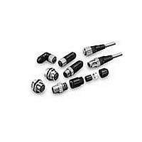
M12 CONNECTOR CABLE, RT. ANGLE DC 5M
Manufacturer
Omron
Series
XS2r
Specifications of XS2F-D422-G80-A
Rohs Compliant
YES
Cable Type
Round
Connector Type
Circular 04 pos Female, Right Angle to Wire Leads
Length
16.40' (5m)
Color
Gray
Shielding
Unshielded
Usage
Industrial Environments - IP67
Product Type
Connectors
Contact Style
Socket (Female)
Shell Style
Receptacle
Number Of Contacts
4
Mounting Style
Threaded
Termination Style
Quick Connect
Current Rating
3 A
Voltage Rating
125 VDC, 250 VAC
Svhc
No SVHC (15-Dec-2010)
Cable Assembly Type
Sensor
Cable Length
5m
Connector Type A
M12 Female Socket
Connector Type B
Free End
Lead Free Status / RoHS Status
Lead free / RoHS Compliant
Lead Free Status / RoHS Status
Lead free / RoHS Compliant
Other names
XS2FD422G80A


Safety Precautions
Refer to Safety Precautions for All Limit Switches.
Operating Environment
Mounting
* By removing the two screws from the head, the head
Group-mounting
guide
(Front: convex
Rear: concave)
• Seal material may deteriorate if a Switch is used outdoor or where subject to special
• Install Switches where they will not be directly subject to cutting
• Constantly subjecting a Switch to vibration or shock can result in
• The Switches have physical contacts. Using them in environments
• Make sure that the plate to which the
• A maximum of 6 Switches may be
• Be sure to tighten each screw to the proper tightening torque as shown in the table.
No.
direction can be rotated 180°. After changing the head
direction, re-tighten to the torque specified above. Be
careful not to allow any foreign substance to enter the
Switch.
(1) M5 Allen-head bolt
(2) M3.5 head mounting screw
(3) M5 Allen-head bolt
cutting oils, solvents, or chemicals. Always appraise performance under actual
application conditions and set suitable maintenance and replacement periods.
chips, dust, or dirt. The Actuator and Switch must also be protected
from the accumulation of cutting chips or sludge.
wear, which can lead to contact interference with contacts,
operation failure, reduced durability, and other problems.
Excessive vibration or shock can lead to false contact operation or
damage. Install Switches in locations not subject to shock and
vibration and in orientations that will not produce resonance.
containing silicon gas will result in the formation of silicon oxide
(SiO
contacts, contact interference can occur. If silicon oil, silicon filling
agents, silicon cables, or other silicon products are present near the
Switch, suppress arcing with contact protective circuits (surge
killers) or remove the source of silicon gas.
D4CC is mounted is flat. If the plate is
warped or has protruding parts, the
D4CC may not malfunction.
group-mounted. In this case, pay attention to the mounting direction so that
the convex part of the group-mounting guide on one Switch fits into the
concave part of the guide on the other Switch as shown in the figure below.
For group mounting, the mounting panel must have a thickness (t) of 6 mm
min.
Group Mounting
Not Suitable
2
) due to arc energy. If silicon oxide accumulates on the
Precautions for Correct Use
Type
16 mm
Appropriate tightening torque *
Suitable
4.90 to 5.88 N·m
4.90 to 5.88 N·m
0.78 to 0.88 N·m
Mounting Holes
Two, 5.2-dia. or
M5 screw holes
25
±
0.1
Mounting plate
t
(3)
(2)
(1)
Operation
• Operation method, shapes of cam and dog, operating frequency,
• To allow the plunger-type actuator to travel properly, adjust the dog
• To allow the roller lever-type actuator to
• Properly adjust the stroke of the center
• Refer to the following to adjust the stroke of
and overtravel have a significant effect on the service life and
precision of a Limit Switch. For this reason, the dog angle must be
30° max., the surface roughness of the dog must be 6.3S min. and
hardness must be Hv400 to 500.
and cam to the proper setting positions. The proper position is
where the plunger groove fits the bushing top.
travel properly, adjust the dog and cam so
that the arrow head is positioned between
the two convex markers as shown below.
roller lever along with the dog or cam so
that the concave part (A) of the head is
located between the convex parts of the
head as shown below when the center
roller lever is pressed by the dog or cam.
the lever based on the mounting hole level.
Bushing top
A
Proper
range
Proper range
Convex parts of head
44.9
(Total Travel Position)
65.3 to 64.6
(Operating Position)
Dog
Groove
Proper range
2.8 mm
Proper
range
Convex
marker
D4CC
Arrow head
A
Proper
range
Proper
range
7
Related parts for XS2F-D422-G80-A
Image
Part Number
Description
Manufacturer
Datasheet
Request
R

Part Number:
Description:
CONNECTOR
Manufacturer:
Omron
Datasheet:

Part Number:
Description:
1M RA SE CONNECTOR,DC,4-PIN
Manufacturer:
Omron
Datasheet:
Part Number:
Description:
2M DC,RA,SE CONNECTOR,4-PIN
Manufacturer:
Omron
Datasheet:
Part Number:
Description:
2mRA SE CONNECTOR,4-PIN VP RBT
Manufacturer:
Omron
Datasheet:
Part Number:
Description:
5mRA SE CONNECTOR,4-PIN VP RBT
Manufacturer:
Omron
Datasheet:
Part Number:
Description:
5M 90 DEG ROBOT CABLE DC 2-PIN
Manufacturer:
Omron
Datasheet:
Part Number:
Description:
2M RA SE CONNECTOR,DC,2-PIN
Manufacturer:
Omron
Datasheet:
Part Number:
Description:
2M RA SE CONNECTOR,DC,3-PIN
Manufacturer:
Omron
Datasheet:
Part Number:
Description:
Sensor I/O Connector
Manufacturer:
Omron
Datasheet: