XS5W-D421-D81-A Omron, XS5W-D421-D81-A Datasheet - Page 16
XS5W-D421-D81-A
Manufacturer Part Number
XS5W-D421-D81-A
Description
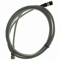
Sensor I/O Connector
Manufacturer
Omron
Series
XS5Wr
Datasheet
1.XS5F-D421-D80-A.pdf
(18 pages)
Specifications of XS5W-D421-D81-A
Connector Type
Circular 04 pos Female to Male
Length
6.56' (2.00m)
Cable Type
Round
Color
Black
Shielding
Unshielded
Usage
Industrial Environments - IP67
Product
I/O Assemblies
Connector End A
Waterproof Smartclick
Connector End B
Waterproof Smartclick
Connector End A Pin Count
4
Connector End B Pin Count
4
Current Rating
4 A
Features
Connected to cable, socket and plug on cable ends
Gender
Female / Male
Voltage Rating
250 VAC
Cable Length - Metric
2m
Jacket Color
Grey
Connector Type B
M12 Sensor 4 Pos. Plug
Connector Type A
M12 Sensor 4 Pos. Receptacle
Cable Assembly Type
Sensor
Lead Free Status / RoHS Status
Lead free / RoHS Compliant
Lead Free Status / RoHS Status
Lead free / RoHS Compliant
Other names
XS5WD421D81A
Z2798
Z2798


(5) Mounting Cap
Note: If the cap is not tighten securely enough, the degree of
(6) After Assembly
Recommended Cables
When connecting a commercially available cable to a connector
assembly, use a cable with an outside diameter of 3 to 6 mm and core
sizes of 0.18 to 0.75 mm
maximum for soldering connectors.
Connector Arrangement
For safety, when constructing a connection system between a Sensor
and panel with a connector, make sure that the connector plug is on
the Sensor side and the connector socket is on the panel side (i.e.,
the female pins are located on the power-supply side).
• Align the triangular marks on the pin block and cover and insert the
• Press them together firmly (0.39 to 0.49 N·m) until the pin block
• After mounting the cover to the pin block and the cover snaps into
• After fully tightening the cap, length A should be approximately one
For 6-mm-dia. cable
For 4-mm-dia. cable
For 3-mm-dia. cable
• Confirm the insulation between cores after completing assembly.
pin block into the cover.
does not come out of the cover.
place, tighten the cap securely by hand within a torque of 0.39 and
0.49 N·m.
of the following according to the cable external diameter and the
Connector model.
Sensor Side
Pin Block
(Screw-mounting Connectors)
(Plug)
protection (IP67) may not be maintained or vibration may
cause the cap to become loose. Do not tighten the cap with
pliers or similar tools; they may damage the cap.
Connector
Cover lock
(Socket)
Connecting Cable
2
for crimping connectors and 0.5 mm
Triangle mark
Pin block
6 mm
---
---
1
Cable external diameter (mm)
Cover
A
5 mm
(Plug)
---
0
2
Cap
Panel Side
(Power-supply Side)
4 mm
---
1
2
(Socket)
3 mm
2
---
---
1
Connecting the XS5
1. Connecting the XS5 Plug and Socket
2. Connecting the XS5 and XS2
• Align the projection on the plug cover with the polarity key on the
• Hold the knurled socket grip, then insert the projection on the plug
• Turn the knurled grips of the socket clockwise approximately 45
• Align the projection on the plug cover with the polarity key on the
• In the same way as when connecting two XS2 Connectors, screw
• Use your fingers to tighten the Connectors sufficiently.
socket, then insert the plug all the way in.
into the groove of the socket.
degrees in respect to the plug. A click will indicate that the
Connectors are locked. The locking condition can also be
confirmed by the alignment marks on the plug and socket.
socket, then insert the plug all the way in.
the knurled grip in the clockwise direction.
Alignment marks
Polarity key
Protrusion on
cover aligns with
polarity key.
XS5
16
Related parts for XS5W-D421-D81-A
Image
Part Number
Description
Manufacturer
Datasheet
Request
R

Part Number:
Description:
Sensor I/O Connector
Manufacturer:
Omron
Datasheet:
Part Number:
Description:
Sensor I/O Connector
Manufacturer:
Omron
Datasheet:
Part Number:
Description:
Sensor I/O Connector
Manufacturer:
Omron
Datasheet: