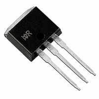
IRGSL4062DPBF International Rectifier, IRGSL4062DPBF Datasheet - Page 5

IRGSL4062DPBF
Manufacturer Part Number
IRGSL4062DPBF
Description
IGBT 600V 24A COPACK TO-262
Manufacturer
International Rectifier
Datasheet
1.IRGS4062DPBF.pdf
(12 pages)
Specifications of IRGSL4062DPBF
Igbt Type
Trench
Voltage - Collector Emitter Breakdown (max)
600V
Vce(on) (max) @ Vge, Ic
1.95V @ 15V, 24A
Current - Collector (ic) (max)
48A
Power - Max
250W
Input Type
Standard
Mounting Type
Through Hole
Package / Case
TO-262-3 (Straight Leads)
Transistor Type
IGBT
Dc Collector Current
48A
Collector Emitter Voltage Vces
1.6V
Collector Emitter Voltage V(br)ceo
600V
Operating Temperature Range
-55°C To +175°C
Transistor Case Style
TO-262
Rohs Compliant
Yes
Channel Type
N
Configuration
Single
Collector-emitter Voltage
600V
Collector Current (dc) (max)
48A
Gate To Emitter Voltage (max)
±20V
Pin Count
3 +Tab
Mounting
Through Hole
Operating Temperature (max)
175C
Operating Temperature Classification
Military
Lead Free Status / RoHS Status
Lead free / RoHS Compliant
www.irf.com
T
J
= 175°C; L = 200µH; V
T
J
= 175°C; L = 200µH; V
1600
1400
1200
1000
1800
1600
1400
1200
1000
800
600
400
200
800
600
400
200
40
35
30
25
20
15
10
0
0
Fig. 15 - Typ. Energy Loss vs. R
0
Fig. 17 - Typ. Diode I
0
0
Fig. 13 - Typ. Energy Loss vs. I
10
10
25
E ON
T
J
20
20
CE
= 175°C
CE
E OFF
R G = 100Ω
50
R G = 47Ω
R G = 22Ω
R G = 10Ω
= 400V, I
= 400V, R
Rg (Ω)
I C (A)
I F (A)
E OFF
30
30
E ON
75
RR
40
40
CE
G
vs. I
= 10Ω; V
= 24A; V
100
F
50
50
C
G
GE
125
GE
60
60
= 15V
= 15V
T
J
T
= 175°C; L = 200µH; V
J
= 175°C; L = 200µH; V
1000
1000
100
100
10
45
40
35
30
25
20
15
10
10
Fig. 16 - Typ. Switching Time vs. R
5
1
Fig. 14 - Typ. Switching Time vs. I
10
Fig. 18 - Typ. Diode I
0
0
t F
td OFF
t R
IRGS/SL4062DPbF
t R
td OFF
25
25
td ON
20
T
J
CE
CE
td ON
= 175°C
50
50
= 400V, R
= 400V, I
R G (Ω)
R G (Ω)
I C (A)
30
RR
75
75
G
CE
vs. R
t F
= 10Ω; V
40
= 24A; V
100
100
G
C
G
GE
125
125
GE
50
= 15V
= 15V
5


