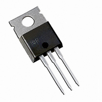
IRG4IBC10UDPBF International Rectifier, IRG4IBC10UDPBF Datasheet

IRG4IBC10UDPBF
Specifications of IRG4IBC10UDPBF
Related parts for IRG4IBC10UDPBF
IRG4IBC10UDPBF Summary of contents
Page 1
... R Junction-to-Case - Diode θJC R Junction-to-Ambient, typical socket mount θJA Wt Weight www.irf.com G ® ultrafast, ultra- n-channel Parameter @ 15V GE @ 15V Parameter PD - 95603B IRG4IBC10UDPbF UltraFast Co-Pack IGBT C CES CE(on) typ (typ.) TO-220AB Max. 600 6.8 3 3.9 27 2500 ± - 150 300 (0.063 in.) (1.6mm from case) ...
Page 2
IRG4IB10UDPbF Electrical Characteristics @ T Parameter V Collector-to-Emitter Breakdown Voltage (BR)CES ∆V /∆T Breakdown Voltage Temp. Coefficient (BR)CES J V Collector-to-Emitter Saturation Voltage CE(on) V Gate Threshold Voltage GE(th) ∆V /∆T Gate Threshold Voltage Coefficient GE(th Forward Transconductance ...
Page 3
... 0 Collector-to-Emitter Voltage (V) CE www.irf.com 1 f, Frequency (KHz) RMS T = 150 15V GE 20µs PULSE WIDTH 10 IRG4IBC10UDPbF 10 100 PK 100 150 50V CC 5µs PULSE WIDTH Gate-to-Emitter Voltage ( ...
Page 4
IRG4IB10UDPbF Case Temperature ( 0.50 1 0.20 0.10 0.05 0.02 0.01 0.1 (THERMAL RESPONSE) 0.01 0.00001 4 100 125 150 ° C) SINGLE PULSE 0.0001 ...
Page 5
... C ies 300 200 C oes 100 C res Collector-to-Emitter Voltage ( 480V 15V GE ° 5.0A C 0.25 0. Gate Resistance (Ohm) G www.irf.com f = 1MHz C SHORTED 100 80 90 100 IRG4IBC10UDPbF 400V 5. Total Gate Charge (nC Ohm 15V 480V CC 1 0.1 0.01 -60 -40 - 100 120 140 160 T , Junction Temperature ( ...
Page 6
IRG4IB10UDPbF 1.4 Ω Ohm 150 C ° 480V 1 15V GE 1.0 0.8 0.6 0.4 0.2 0 Collector-to-emitter Current ( 100 10 ...
Page 7
... V = 200V 125° 25°C J 160 4.0A F 120 100 di /dt - (A/µs) f www.irf.com 200V 125° 25° 1000 100 f 1000 V = 200V 125° 25° 8. 4.0A F 100 1000 100 f IRG4IBC10UDPbF 1000 di /dt - (A/µ 1000 di /dt - (A/µs) f (rec ...
Page 8
IRG4IB10UDPbF 430µF 80% of Vce LM on off(diode) rr 10% +Vg Vce 10% Ic Vcc 5% Vce tr td(on Same type device as +Vge D.U.T. D.U. d(on) r d(off) f GATE VOLTAGE D.U.T. +Vg DUT VOLTAGE ...
Page 9
... Figure 18e. Macro Waveforms for 50V 6000µF 100V Figure 19. Clamped Inductive Load Test Circuit www.irf.com Vg GATE SIGNAL Figure 18a's D.U.T. L 1000V IRG4IBC10UDPbF DEVICE UNDER TEST CURRENT D.U.T. VOLTAGE IN D.U.T. CURRENT IN D1 Test Circuit L Figure 20. Pulsed Collector Current Test Circuit C 9 ...
Page 10
IRG4IB10UDPbF TO-220AB Full-Pak Package Outline Dimensions are shown in millimeters (inches) TO-220AB Full-Pak Part Marking Information TO-220AB Full-Pak package is not recommended for Surface Mount Application. Notes: Repetitive rating 20V, pulse width limited by max. junction temperature ...


