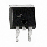
IRGS8B60KPBF International Rectifier, IRGS8B60KPBF Datasheet - Page 2

IRGS8B60KPBF
Manufacturer Part Number
IRGS8B60KPBF
Description
IGBT ULTRA FAST 600V 28A D2PAK
Manufacturer
International Rectifier
Datasheet
1.IRGB8B60KPBF.pdf
(13 pages)
Specifications of IRGS8B60KPBF
Igbt Type
NPT
Voltage - Collector Emitter Breakdown (max)
600V
Vce(on) (max) @ Vge, Ic
2.2V @ 15V, 8A
Current - Collector (ic) (max)
28A
Power - Max
167W
Input Type
Standard
Mounting Type
Surface Mount
Package / Case
D²Pak, TO-263 (2 leads + tab)
Collector Emitter Voltage Vces
2.2V
Power Dissipation Pd
167W
Collector Emitter Voltage V(br)ceo
600V
Continuous Collector Current Ic
28A
Collector Emitter Saturation Voltage Vce(sat)
2.2V
Rohs Compliant
Yes
Package
D2-Pak
Circuit
Discrete
Switching
Hard
Switching Speed
ULTRAFAST 8-30 kHz
Vces (v)
600
Ic @ 25c (a)
28
Ic @ 100c (a)
19
Vce(on)@25c Typ (v)
1.80
Vce(on)@25c Max (v)
2.2
Ets Typ (mj)
0.32
Ets Max (mj)
0.433
Pd @25c (w)
167
Environmental Options
PbF
Lead Free Status / RoHS Status
Lead free / RoHS Compliant
Other names
*IRGS8B60KPBF
IRGB/S/SL8B60KPbF
Notes
V
∆V
V
V
∆V
gfe
I
I
Q
Q
Q
E
E
E
t
t
t
t
E
E
E
t
t
t
t
C
C
C
RBSOA
SCSOA
Electrical Characteristics @ T
Switching Characteristics @ T
CES
GES
d(on)
r
d(off)
f
d(on)
r
d(off)
f
(BR)CES
CE(on)
GE(th)
on
off
tot
on
off
tot
ies
oes
res
g
ge
gc
(BR)CES
GE(th)
2
/∆T
to … are on page 13.
/∆T
J
J
Collector-to-Emitter Breakdown Voltage
Temperature Coeff. of Breakdown Voltage
Collector-to-Emitter Voltage
Gate Threshold Voltage
Threshold Voltage temp. coefficient
Forward Transconductance
Zero Gate Voltage Collector Current
Gate-to-Emitter Leakage Current
Total Gate Charge (turn-on)
Gate-to-Emitter Charge (turn-on)
Gate-to-Collector Charge (turn-on)
Turn-On Switching Loss
Turn-Off Switching Loss
Total Switching Loss
Turn-On delay time
Rise time
Turn-Off delay time
Fall time
Turn-On Switching Loss
Turn-Off Switching Loss
Total Switching Loss
Turn-On delay time
Rise time
Turn-Off delay time
Fall time
Input Capacitance
Output Capacitance
Reverse Transfer Capacitance
Reverse Bias Safe Operating Area
Short Circuit Safe Operating Area
Parameter
Parameter
J
J
= 25°C (unless otherwise specified)
= 25°C (unless otherwise specified)
Min. Typ. Max. Units
Min. Typ. Max. Units
600
3.5
10
—
—
—
—
—
—
—
—
—
—
—
—
—
—
—
—
—
—
—
—
—
—
—
—
—
—
—
—
—
—
FULL SQUARE
0.57
-9.5
200
800
160
160
320
140
220
270
490
180
440
1.8
2.2
2.3
4.5
3.7
1.0
3.7
29
14
23
22
32
22
21
40
38
16
—
—
—
1320
±100
150
500
268
268
433
150
330
381
608
198
2.2
2.5
2.6
5.5
27
26
42
27
25
56
—
—
—
—
—
—
—
—
—
—
—
mV/°C V
V/°C V
µA V
nA V
nC V
pF V
µJ
ns
µJ
ns
µs
V
V
S
V
V
V
V
V
I
V
I
V
T
I
V
T
I
V
T
I
V
T
V
f = 1.0MHz
T
V
T
V
I
I
I
C
C
C
C
C
C
C
C
GE
GE
CE
CE
CE
GE
GE
GE
GE
CC
GE
GE
J
GE
J
GE
J
GE
J
GE
CC
J
CC
J
CC
= 8.0A
= 8.0A, V
= 8.0A, V
= 8.0A, V
= 8.0A, V
= 25°C
= 25°C
= 150°C
= 150°C
= 150°C, I
= 150°C, Vp = 600V, R
= 8.0A, V
= 8.0A, V
= 8.0A, V
=500V,V
=360V,V
= 0V, I
= 0V, I
= V
= V
= 50V, I
= 0V, V
= 0V, V
= 0V, V
= ±20V
= 480V
= 15V, R
= 15V, R
= 15V, R
= 15V, R
= 0V
= 30V
Conditions
= 15V
GE
GE
, I
, I
C
C
CC
CC
CC
CC
C
C
CE
CE
CE
C
GE
GE
GE
GE
GE
= 500µA
= 1mA (25°C-150°C)
C
G
G
G
G
Conditions
= 250µA
= 1mA (25°C-125°C)
= 8.0A, PW = 80µs
= 600V
= 600V, T
= 600V, T
= 400V
= 400V
= 400V
= 400V
= 34A, Vp = 600V
= 50Ω, L = 1.1mH
= 50Ω, L = 1.1mH
= 50Ω, L = 1.1mH
= 50Ω, L = 1.1mH
= 15V, T
= 15V, T
= 15V, T
= +15V to 0V,R
= +15V to 0V
J
J
J
J
J
= 25°C
= 150°C
= 175°C
= 150°C
= 175°C
G
= 100Ω
www.irf.com
G
= 50Ω
Ref.Fig.
Ref.Fig.
WF1,WF2
8,9,10,
8,9,10
12,14
13,15
5,6,7
WF1
WF2
WF3
CT1
CT4
CT4
CT4
CT4
CT2
CT3
11
17
16
4


