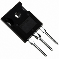
IRGP30B120KDPBF International Rectifier, IRGP30B120KDPBF Datasheet - Page 2

IRGP30B120KDPBF
Manufacturer Part Number
IRGP30B120KDPBF
Description
IGBT 1200V 60A W/DIODE TO-247AC
Manufacturer
International Rectifier
Specifications of IRGP30B120KDPBF
Igbt Type
NPT
Voltage - Collector Emitter Breakdown (max)
1200V
Vce(on) (max) @ Vge, Ic
4V @ 15V, 60A
Current - Collector (ic) (max)
60A
Power - Max
300W
Input Type
Standard
Mounting Type
Through Hole
Package / Case
TO-247-3 (Straight Leads), TO-247AC
Lead Free Status / RoHS Status
Lead free / RoHS Compliant
IRGP30B120KD-EP
∆V
∆V
V
V
V
g
I
V
I
Q
Q
Q
E
E
E
E
E
E
td(on)
tr
td(off)
tf
C
C
C
RBSOA
SCSOA
E
trr
Irr
Le
Electrical Characteristics @ TJ = 25°C (unless otherwise specified)
Switching Characteristics @ T
CES
GES
fe
(BR)CES
CE(on)
GE(th)
FM
on
off
tot
on
off
tot
rec
ies
oes
res
g
ge
gc
2
(BR)CES
GE(th)
/ ∆Tj
/ ∆Tj
Collector-to-Emitter Breakdown Voltage
Temperature Coeff. of Breakdown Voltage
Gate Threshold Voltage
Temperature Coeff. of Threshold Voltage
Forward Transconductance
Zero Gate Voltage Collector Current
Diode Forward Voltage Drop
Gate-to-Emitter Leakage Current
Total Gate charge (turn-on)
Gate - Emitter Charge (turn-on)
Gate - Collector Charge (turn-on)
Turn-On Switching Loss
Turn-Off Switching Loss
Total Switching Loss
Turn-on Switching Loss
Turn-off Switching Loss
Total Switching Loss
Turn - on delay time
Rise time
Turn - off delay time
Fall time
Input Capacitance
Output Capacitance
Reverse Transfer Capacitance
Reverse bias safe operating area
Short Circuit Safe Operating Area
Reverse recovery energy of the diode
Diode Reverse recovery time
Peak Reverse Recovery Current
Internal Emitter Inductance
Collector-to-Emitter Saturation
Parameter
Parameter
Voltage
J
= 25°C (unless otherwise specified)
1200
Min.
Min.
14.8
4.0
10
FULL SQUARE
1066
1493
2559
1660
2118
3778
2200
1820
Typ.
- 1.2
Typ.
+1.2
2.28
2.46
3.43
2.74
2.98
16.9
1.76
1.86
1.87
2.01
325
169
210
210
300
5.0
----
19
82
50
25
60
85
34
13
Max. Units
2000
±100
Max. Units
1250
1800
3050
1856
2580
4436
2400
2.48
2.66
4.00
3.10
3.35
19.0
2.06
2.17
2.18
2.40
250
675
254
123
230
6.0
----
29
65
35
75
38
mV/
V/°C
nC
nH
µA
nA
pF
µJ
µJ
ns
µs
µJ
ns
V
V
V
S
V
A
o
C
V
V
I
I
I
I
I
V
V
V
V
V
V
I
I
I
I
V
I
V
V
I
V
T
and diode reverse recovery
Ic =25A, V
V
T
and diode reverse recovery
Ic =25A, V
V
T
V
V
f = 1.0 MHz
T
V
Rg = 5Ω, V
T
V
Rg = 5Ω, V
T
V
V
Measured 5 mm from the package.
C
C
C
C
C
C
C
C
C
C
C
J
J
GE
GE
CE
CE
CE
GE
GE
GE
GE
CC
GE
GE
GE
GE
J
GE
CC
J
CC
J
CC
J
CC
GE
= 25A, V
= 30A, V
= 60A, V
= 25A, V
= 30A, V
= 25A
= 30A
= 25A, T
= 30A, T
= 25A
= 25A, V
= 25
= 125
= 125
=150
= 150
= 125
= 0V,I
= 0V, I
= V
= V
= 50V, I
= 0V,V
= 0v, V
= 0v, V
= ±20V
=600V
= 15V
= 15V, Rg = 5Ω, L =200µH
= 15V, Rg = 5Ω, L =200µH
= 15V, Rg = 5Ω, L =200µH
= 0V
= 30V
= 1000V, V
= 900V,V
= 600V, Ic = 25A
= 15V, Rg = 5Ω, L =200µH
o
C, Energy losses include tail
o
GE
GE
o
C, Energy losses include tail
o
o
o
C, Ic = 120A
C,
C
C
, I
, I
c
CC
CC
c
J
J
GE
GE
GE
GE
GE
CE
CC
GE
GE
Conditions
=250 µA
CE
CE
Conditions
C
C
= 1 mA ( 25 -125
C
= 125°C
= 125°C
=600V
=600V
= 250 µA
= 1 mA ( 25 -125
P
= 15V
= 15V
= 15V
= 15V, T
= 15V, T
= 25A, PW=80µs
= 1200V
= 600V
= +15V to 0 V
= +15V to 0 V
= 1200V, T
= 1200V, T
= 1200V
P
= 1200V
J
J
= 125°C
= 125°C
J
J
=125°C
=150°C
www.irf.com
o
C )
o
C )
9 ,1 0 ,1 1 ,1 2
CT 4 , WF3
1 7 ,1 8 ,1 9
WF1 & 2
1 3 , 1 5
1 4 , 1 6
2 0 , 2 1
Fig.
Fig.
WF1
WF2
WF1
WF2
WF4
5 , 6
7 , 9
CT 1
CT 4
CT 4
CT 4
CT 2
CT 3
1 0
1 1
2 3
2 2
8
4


