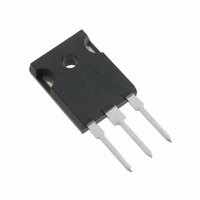
IRG7PH35UPBF International Rectifier, IRG7PH35UPBF Datasheet - Page 6

IRG7PH35UPBF
Manufacturer Part Number
IRG7PH35UPBF
Description
IGBT N-CH 1200V 55A TO-247AC
Manufacturer
International Rectifier
Datasheet
1.IRG7PH35UPBF.pdf
(10 pages)
Specifications of IRG7PH35UPBF
Igbt Type
Trench
Voltage - Collector Emitter Breakdown (max)
1200V
Vce(on) (max) @ Vge, Ic
2.2V @ 15V, 20A
Current - Collector (ic) (max)
55A
Power - Max
210W
Input Type
Standard
Mounting Type
Through Hole
Package / Case
TO-247-3 (Straight Leads), TO-247AC
Transistor Type
IGBT
Dc Collector Current
55A
Collector Emitter Voltage Vces
1.9V
Collector Emitter Voltage V(br)ceo
1.2kV
Operating Temperature Range
-55°C To +175°C
Transistor Case Style
TO-247AC
Rohs Compliant
Yes
Lead Free Status / RoHS Status
Lead free / RoHS Compliant
Available stocks
Company
Part Number
Manufacturer
Quantity
Price
IRG7PH35UPbF/IRG7PH35U-EP
6
Fig. 18 - Typical Gate Charge vs. V
16
14
12
10
8
6
4
2
0
0
0.001
0.01
0.1
1
1E-006
I
CE
20
Q G , Total Gate Charge (nC)
= 20A; L = 2.4mH
V CES = 600V
V CES = 400V
Fig 20. Maximum Transient Thermal Impedance, Junction-to-Case
D = 0.50
40
0.10
0.02
0.20
0.05
0.01
SINGLE PULSE
( THERMAL RESPONSE )
60
1E-005
80
GE
100
t 1 , Rectangular Pulse Duration (sec)
0.0001
τ
J
τ
J
τ
1
Ci= τi/Ri
τ
1
Ci
i/Ri
R
1
R
1
τ
2
0.001
R
τ
2
2
R
1.0
0.8
0.6
0.4
2
25
Fig. 19 - Typical Gate Threshold Voltage
R
τ
(Normalized) vs. Junction Temperature
3
3
R
τ
3
3
Notes:
1. Duty Factor D = t1/t2
2. Peak Tj = P dm x Zthjc + Tc
50
τ
R
4
τ
4
R
4
4
T J , Temperature (°C)
τ
C
τ
75
Ri (°C/W)
0.01
0.017
0.218
0.299
0.177
100
0.000013
0.000141
0.002184
0.013107
τi (sec)
125
I C = 600μA
150
0.1
www.irf.com
175


