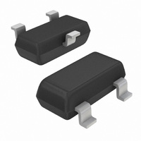
MMBFU310LT1G ON Semiconductor, MMBFU310LT1G Datasheet - Page 2

MMBFU310LT1G
Manufacturer Part Number
MMBFU310LT1G
Description
JFET SS N-CH 25V SOT23
Manufacturer
ON Semiconductor
Datasheet
1.MMBFU310LT1G.pdf
(4 pages)
Specifications of MMBFU310LT1G
Current - Drain (idss) @ Vds (vgs=0)
24mA @ 10V
Drain To Source Voltage (vdss)
25V
Fet Type
N-Channel
Voltage - Breakdown (v(br)gss)
25V
Voltage - Cutoff (vgs Off) @ Id
2.5V @ 1nA
Input Capacitance (ciss) @ Vds
5pF @ 10V (VGS)
Mounting Type
Surface Mount
Package / Case
TO-236-3, SC-59, SOT-23-3
Power - Max
225mW
Configuration
Single
Transistor Polarity
N-Channel
Drain Source Voltage Vds
25 V
Gate-source Breakdown Voltage
25 V
Drain Current (idss At Vgs=0)
24 mA to 60 mA
Maximum Operating Temperature
+ 150 C
Minimum Operating Temperature
- 55 C
Mounting Style
SMD/SMT
Transistor Type
JFET
Breakdown Voltage Vbr
-25V
Zero Gate Voltage Drain Current Idss
24mA To 60mA
Gate-source Cutoff Voltage Vgs(off) Max
-6V
Power Dissipation Pd
225mW
Rohs Compliant
Yes
Lead Free Status / RoHS Status
Lead free / RoHS Compliant
Other names
MMBFU310LT1GOS
MMBFU310LT1GOS
MMBFU310LT1GOSTR
MMBFU310LT1GOS
MMBFU310LT1GOSTR
Available stocks
Company
Part Number
Manufacturer
Quantity
Price
Company:
Part Number:
MMBFU310LT1G
Manufacturer:
ON Semiconductor
Quantity:
4 450
Company:
Part Number:
MMBFU310LT1G
Manufacturer:
ON
Quantity:
30 000
Part Number:
MMBFU310LT1G
Manufacturer:
ON/安森美
Quantity:
20 000
ELECTRICAL CHARACTERISTICS
OFF CHARACTERISTICS
ON CHARACTERISTICS
SMALL−SIGNAL CHARACTERISTICS
Gate−Source Breakdown Voltage − (I
Gate 1 Leakage Current − (V
Gate 2 Leakage Current − (V
Gate Source Cutoff Voltage − (V
Zero−Gate−Voltage Drain Current − (V
Gate−Source Forward Voltage − (I
Forward Transfer Admittance − (V
Output Admittance − (V
Input Capacitance − (V
Reverse Transfer Capacitance − (V
60
50
40
30
20
10
70
-5.0
I
Characteristics vs Gate−Source Voltage
DSS
Figure 1. Drain Current and Transfer
- V
I
-4.0
V
D
DS
GS
- V
, GATE-SOURCE CUTOFF VOLTAGE (VOLTS)
= 10 V
GS
, GATE-SOURCE VOLTAGE (VOLTS)
GS
I
+ 25°C
DS
DSS
-3.0
= −10 Vdc, V
= 10 Vdc, I
GS
GS
DS
= −15 Vdc, V
= −15 Vdc, V
DS
G
Characteristic
= 10 Vdc, I
GS
= 10 mAdc, V
-2.0
G
= 10 Vdc, I
D
DS
= −10 Vdc, V
DS
= −1.0 mAdc, V
= 10 mAdc, f = 1.0 kHz)
(T
= 10 Vdc, V
= 0 Vdc, f = 1.0 MHz)
A
= 25°C unless otherwise noted)
- 55°C
DS
DS
D
T
D
A
= 1.0 nAdc)
= 0)
= 0, T
-1.0
+ 25°C
= - 55°C
DS
= 10 mAdc, f = 1.0 kHz)
DS
= 0)
GS
DS
A
+150°C
+150°C
= 0 Vdc, f = 1.0 MHz)
+ 25°C
= 125°C)
http://onsemi.com
= 0)
= 0)
0
70
60
50
40
30
20
10
0
2
5.0
35
30
25
20
15
10
0
5.0
V
f = 1.0 MHz
DS
Figure 2. Forward Transconductance
= 10 V
4.0
V
V
Symbol
V
GS
(BR)GSS
V
I
I
G1SS
G2SS
GS(off)
I
|y
|Y
C
C
DSS
vs Gate−Source Voltage
GS(f)
, GATE-SOURCE VOLTAGE (VOLTS)
os
rss
iss
fs
|
|
3.0
−2.5
−25
Min
24
10
−
−
−
−
−
−
2.0
- 55°C
T
A
+150°C
= - 55°C
−150
−150
−6.0
Max
250
1.0
5.0
2.5
60
18
−
+150°C
1.0
+ 25°C
+ 25°C
mmhos
mmhos
mAdc
nAdc
Unit
Vdc
Vdc
Vdc
pA
pF
pF
0


