2N7002V-7 Diodes Inc, 2N7002V-7 Datasheet

MOSFET 2N-CH 60V 280MA SOT-563

2N7002V-7

Manufacturer Part Number
2N7002V-7
Description
MOSFET 2N-CH 60V 280MA SOT-563
Manufacturer
Diodes Inc
Datasheet

Specifications of 2N7002V-7

Fet Type
2 N-Channel (Dual)
Fet Feature
Standard
Rds On (max) @ Id, Vgs
7.5 Ohm @ 50mA, 5V
Drain To Source Voltage (vdss)
60V
Current - Continuous Drain (id) @ 25° C
280mA
Vgs(th) (max) @ Id
2.5V @ 250µA
Input Capacitance (ciss) @ Vds
50pF @ 25V
Power - Max
150mW
Mounting Type
Surface Mount
Package / Case
SOT-563
Configuration
Dual
Transistor Polarity
N-Channel
Resistance Drain-source Rds (on)
7.5 Ohm @ 5 V
Forward Transconductance Gfs (max / Min)
0.08 S
Drain-source Breakdown Voltage
60 V
Gate-source Breakdown Voltage
+/- 20 V
Continuous Drain Current
0.28 A
Power Dissipation
150 mW
Maximum Operating Temperature
+ 150 C
Mounting Style
SMD/SMT
Minimum Operating Temperature
- 55 C
Lead Free Status / RoHS Status
Lead free / RoHS Compliant
Gate Charge (qg) @ Vgs
-
Lead Free Status / Rohs Status
Lead free / RoHS Compliant
Other names
2N7002VDITR
Features
·
·
·
·
·
·
·
·
·
·
·
·
·
·
·
·
·
·
Maximum Ratings
Notes:
DS30448 Rev. 2 - 2
Mechanical Data
Drain-Source Voltage
Drain-Gate Voltage R
Gate-Source Voltage (Note 3)
Drain Current (Note 3)
Total Power Dissipation
Thermal Resistance, Junction to Ambient
Operating and Storage Temperature Range
Dual N-Channel MOSFET
Low On-Resistance
Low Gate Threshold Voltage
Low Input Capacitance
Fast Switching Speed
Low Input/Output Leakage
Ultra-Small Surface Mount Package
Lead Free Plating
Case: SOT-563, Molded Plastic
Case Material - UL Flammability Rating 94V-0
Moisture sensitivity: Level 1 per J-STD-020A
Terminals: Solderable per MIL-STD-202,
Method 208
Terminals: Finish - Matte Tin (Note 2) Solderable
per MIL-STD-202, Method 208
Terminal Connections: See Diagram
Marking (See Page 2): KAS & KAY
Ordering & Date Code Information: See Page 2
Weight: 0.006 grams (approx.)
2. If lead-bearing terminal plating is required, please contact your Diodes Inc. sales representative for availability and minimum
3. Device mounted on FR-4 PCB, 1 inch x 0.85 inch x 0.062 inch; pad layout as shown on Diodes Inc. suggested pad layout
1. Package is non-polarized. Parts may be on reel in orientation illustrated, 180° rotated, or mixed (both ways).
order details.
document AP02001, which can be found on our website at http://www.diodes.com/datasheets/ap02001.pdf.
Characteristic
GS
£ 1.0MW
@ T
A
= 25°C unless otherwise specified
Continuous
Continuous
Pulsed
Pulsed
www.diodes.com
1 of 3
K
(KAS Marking Code)
Symbol
T
V
V
V
j
R
, T
I
KAx YM
DGR
P
D
S
DSS
GSS
I
DM
qJA
D
2
2
2N7002V
d
STG
G
G
G
H
A
1
2
D
DUAL N-CHANNEL ENHANCEMENT
S
D
MODE FIELD EFFECT TRANSISTOR
1
1
SEE NOTE 1
B C
M
L
-55 to +150
Value
±20
±40
280
150
833
1.5
60
60
2N7002V/VA
SPICE MODEL: 2N7002V/VA
(KAY Marking Code)
D
G
2N7002VA
2
2
Dim
G
M
A
B
C
D
H
K
L
S
S
All Dimensions in mm
1
2
G
D
0.15
1.10
1.55
0.90
1.50
0.56
0.10
0.10
Min
1
1
ã
SOT-563
Diodes Incorporated
Units
°C/W
mW
mA
2N7002V/VA
°C
0.50
V
V
V
A
Max
0.30
1.25
1.70
1.10
1.70
0.60
0.30
0.18
0.25
1.20
1.60
1.00
1.60
0.60
0.20
0.11
Typ

Related parts for 2N7002V-7

2N7002V-7 Summary of contents

Page 1

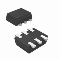
... Marking Code) Symbol V DSS V DGR Continuous V GSS Pulsed Continuous I D Pulsed qJA STG www.diodes.com 2N7002V/VA SPICE MODEL: 2N7002V/VA SOT-563 Dim Min Max Typ A 0.15 0.30 0.25 B 1.10 1.25 1.20 C 1.55 1.70 1.60 D 0.50 G 0.90 1.10 1.00 H 1.50 1.70 1. ...

Page 2

... Input Capacitance Output Capacitance Reverse Transfer Capacitance SWITCHING CHARACTERISTICS Turn-On Delay Time Turn-Off Delay Time Ordering Information (Note 5) Device 2N7002V-7 2N7002VA-7 Notes: 4. Short duration test pulse used to minimize self-heating effect. 5. For Packaging Details our website at http://www.diodes.com/datasheets/ap02007.pdf. Marking Information KAS = 2N7002V Product Type Marking Code ...

Page 3

... T , AMBIENT TEMPERATURE (°C) A Fig. 1, Derating Curve - Total DS30448 Rev 100 150 www.diodes.com 2N7002V/VA ...

Related keywords