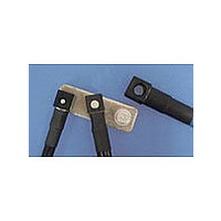
6648221-1 TE Connectivity, 6648221-1 Datasheet - Page 34

6648221-1
Manufacturer Part Number
6648221-1
Description
Power to the Board CONTACT PIN #8
Manufacturer
TE Connectivity
Type
Quick Disconnect Terr
Datasheet
1.6648221-1.pdf
(111 pages)
Specifications of 6648221-1
Body Plating
Silver Over Nickel
Body Material
Copper Alloy
Product Type
Contact
Product Line
RAPID LOCK
Pcb Mounting Orientation
Vertical
Current Rating (a)
120
Pin Type
Swage
Mount Type
Backplane, Bus Bar
Voltage Drop (mv)
20
Pin Material
Copper Alloy
Pin Plating
Silver over Nickel
Contact Type
Pin
Contact Size
8
Rohs/elv Compliance
RoHS compliant, ELV compliant
Lead Free Solder Processes
Not relevant for lead free process
Rohs/elv Compliance History
Always was RoHS compliant
Lead Free Status / RoHS Status
Compliant
Crimp Snap-In Contacts
(Hermaphroditic)
Material and Finish
Phosphor bronze, plated gold in contact
area (for length of .236 [6.0] from tip),
with entire contact underplated nickel
Related Product Data
Performance Specifications —
page 92
Housings — page 94
Technical Documents
Instruction Sheets
408-097J, 408-098J, 408-151J
Recommended Panel Cutout
Catalog 1773096
Revised 2-10
www.tycoelectronics.com
Dimensions are in inches and
millimeters unless otherwise
specified. Values in brackets
are metric equivalents.
Power Connectors & Interconnection Systems
Standard Blind-Mate Drawer Connectors
Note: All part numbers are RoHS compliant.
*Applicators are for Model “K” machines. Consult Tyco Electronics for applicators for other bench machines and lead-
Notes: 1. For applicable wire, use wire specified in UL 1015 or 1007.
Notes:
Extraction Tool Part Number 723986-1
Note: Mounting holes of .209 [5.30] dia. are used when mounting receptacle housings with .157 [4.0] long floating
making machines.
24-20
20-16
18-14
AWG
Wire Size Range
bushings and the mating plug housings. Panel thickness is .063 [1.60]. Panel cutout shown above is for use
with plug housings. For receptacle housings, use the mirror-image cutout.
2. Contacts for 18-14 AWG [0.8-2.0 mm
tacts (8 required per assembly).
0.2-0.6
0.5-1.4
0.8-2.0
mm
[4.30
[5.30
.169
.209
(2 Plcs.)
2
±.012
±0.30
±.012
±0.30
J
Dimensions are shown for
reference purposes only.
Specifications subject
to change.
K [
] or
] Dia.
±.0.30
±.012
Rear Panel-Mount
[13.30
Dia. Range
Insulation
.524
.059-.077
1.50-1.95
.071-.130
1.80-3.30
.091-.154
2.30-3.90
L [
[5.30
]
.209
(2 Plcs.)
±.0.30
±.012
[3.20]
[3.70]
.126
.146
±.012
±0.30
±.012
±0.30
]
]
]
[0.20R]
Max.
.008
[2.70
.106
(2 Plcs.)
Strip Form
±.012
±0.30
[20.1]
.791
170311-1
170484-1
170312-1
[23.90
2
.941
] wire are used at the four corners of the connector as power con-
[5.30]
]
.209
USA: 1-800-522-6752
Canada: 1-905-470-4425
Mexico: 01-800-733-8926
C. America: 52-55-1106-0803
±.012
±0.30
Contact
]
Loose Piece
170313-1
170485-1
170314-1
(Continued)
No. of
Part Numbers
Pos.
12
16
20
24
8
Rear Panel-Mount Dimensions
1.913
48.60
2.307
58.60
2.701
68.60
3.094
78.60
3.488
88.60
AMP-O-LECTRIC
J
Applicator for
Machine*
567324-2
567241-2
567325-2
South America: 55-11-2103-6000
Hong Kong: 852-2735-1628
Japan: 81-44-844-8013
UK: 44-(0)8002-67666
CERTI-CRIMP Hand Tool
Part Number 91591-1
1.500
38.00
1.890
48.00
2.283
58.00
2.677
68.00
3.071
78.00
K
1.110
28.20
1.504
38.20
1.898
48.20
2.291
58.20
2.685
68.20
Hand Tool
2063849-1
Numbers
L
91591-1
91590-1
95


