320573 TE Connectivity, 320573 Datasheet - Page 5
320573
Manufacturer Part Number
320573
Description
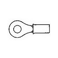
TERMINAL, RING TONGUE, 3/8IN, CRIMP, RED
Manufacturer
TE Connectivity
Type
Ring Tongue Terminalr
Series
PIDGr
Specifications of 320573
Stud Size
9.53mm
Wire Gauge
16-22
Body Plating
Tin
Body Material
Copper
Insulation
Nylon
Product Depth (mm)
13.49mm
Product Length (mm)
30.94mm
Color
Red
Connector Type
Ring Tongue
Insulator Color
Red
Termination Method
Crimp
Stud/tab Size
0.375"
Wire Size (awg)
22-16
Contact Material
Copper
Contact Plating
Tin
Rohs Compliant
Yes
Angle
Straight
Brand/series
PIDG
Diameter, Insulation
0.125 "
Insulation Type
Nylon
Length, Overall
1.218 "
Material, Contact
Copper
Primary Type
Ring
Size, Stud
3⁄8 "
Width, Overall
0.531 "
Wire Size
22-16 AWG
Terminal Shape
Ring Tongue
Receptacle Style
Straight
Body Style
PIDG
Barrel Type
Closed Barrel
Wire/cable Type
Regular Wire
Insulation Support
Insulation Support
Insulation Diameter (mm [in])
2.03-3.18 [.080-.125]
Stud Diameter (mm [in])
9.53 [0.375]
Shape
RING-041
Heavy Duty
No
Finish
Tin
Insulation Material
Nylon
Voltage (vac)
300
Wire/cable Size (cma)
509 – 3,260
Wire Range (mm [awg])
0.30-1.40² [22-16]
Tongue Material Thickness (mm [in])
0.79 [0.031]
Class
1 & 2
Government/industry Qualification
Yes
Government/industry Part Number
MS25036-105
Rohs/elv Compliance
RoHS compliant, ELV compliant
Lead Free Solder Processes
Not relevant for lead free process
Rohs/elv Compliance History
Always was RoHS compliant
Packaging Method
Loose Piece
Packaging Quantity
1,000
Lead Free Status / RoHS Status
Compliant


3.4. Wire Placement
The stripped wire must be inserted into the wire barrel until the wire insulation is against the wire barrel but not
inside it. The wire insulation must be inside the metal sleeve. A gap between the wire insulation and wire barrel
is allowed, but not to exceed the dimension given in Figure 3.
3.5. Crimp Requirements
C
F
Produced by Crescent Crimp Tooling
Produced by TETRA–CRIMP Tooling
NOTE
Crimp Inspection Using Micrometer or Comparator
D
A. Crimp Height
The spring–back of the terminal, splice, or end cap insulation prevents an accurate direct measurement of
crimp height. However, crimping a slug of solder (60% tin and 40% lead) with a diameter slightly larger
than the conductor outside diameter can verify proper termination. The crimp height of the resulting solder
slug can be checked with a standard micrometer or comparator. The measurement must be made over
the most compressed area of the solder slug. See Figure 4.
Transparent Insulation
Window Butt Splice Shown
Some tooling with multiple crimping chambers form an embossed dot code in the terminal, splice, or end cap
insulation that indicates which crimping chamber was used. This dot code can be used as a visual inspection to ensure
that the correct wire size and crimping chamber were used.
PIDG Terminals, Splices, and End Caps
Figure 4 (Cont’d)
Figure 3
Wire Barrel Crimp Profile and Location
114-2157
5
Related parts for 320573
Image
Part Number
Description
Manufacturer
Datasheet
Request
R

Part Number:
Description:
TERMINAL, SPADE/FORK, #10, CRIMP, BLUE
Manufacturer:
TE Connectivity
Datasheet:

Part Number:
Description:
Printers THERMAL PRINTER HS-SLEEVE MARKER
Manufacturer:
TE Connectivity


Part Number:
Description:
High Speed / Modular Connectors 30P HEADER ASSY
Manufacturer:
TE Connectivity
Datasheet:

Part Number:
Description:
High Speed / Modular Connectors REC 6X005P R/A LT B-PLANE HS3
Manufacturer:
TE Connectivity
Datasheet:

Part Number:
Description:
High Speed / Modular Connectors 2MM HM RCPT 50P R/A AU
Manufacturer:
TE Connectivity
Datasheet:

Part Number:
Description:
High Speed / Modular Connectors 2MM HM RCPT 50P R/A AU
Manufacturer:
TE Connectivity
Datasheet:


Part Number:
Description:
Manufacturer:
TE Connectivity
Datasheet:


Part Number:
Description:
Manufacturer:
TE Connectivity
Datasheet:

Part Number:
Description:
Manufacturer:
TE Connectivity
Datasheet:

Part Number:
Description:
Manufacturer:
TE Connectivity
Datasheet: