TP0610KL-TR1-E3 Vishay, TP0610KL-TR1-E3 Datasheet - Page 2
TP0610KL-TR1-E3
Manufacturer Part Number
TP0610KL-TR1-E3
Description
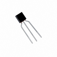
MOSFET P-CH 60V 270MA TO92-3
Manufacturer
Vishay
Series
TrenchFET®r
Datasheet
1.TP0610KL-TR1-E3.pdf
(5 pages)
Specifications of TP0610KL-TR1-E3
Fet Type
MOSFET P-Channel, Metal Oxide
Fet Feature
Standard
Rds On (max) @ Id, Vgs
6 Ohm @ 500mA, 10V
Drain To Source Voltage (vdss)
60V
Current - Continuous Drain (id) @ 25° C
270mA
Vgs(th) (max) @ Id
3V @ 250µA
Gate Charge (qg) @ Vgs
3nC @ 15V
Power - Max
800mW
Mounting Type
Through Hole
Package / Case
TO-92-3 (Standard Body), TO-226
Transistor Polarity
P Channel
Continuous Drain Current Id
-270mA
Drain Source Voltage Vds
-60V
On Resistance Rds(on)
6ohm
Rds(on) Test Voltage Vgs
20V
Threshold Voltage Vgs Typ
-2.1V
Lead Free Status / RoHS Status
Lead free / RoHS Compliant
Other names
TP0610KL-TR1-E3TR


TP0610KL/BS250KL
Vishay Siliconix
Notes
a.
b.
www.vishay.com
2
For the following graphs, p-channel negative polarities for all voltage and current values are represented as positive values.
SPECIFICATIONS (T
Static
Drain-Source Breakdown Voltage
Gate-Threshold Voltage
Gate Body Leakage
Gate-Body Leakage
Zero Gate Voltage Drain Current
Zero Gate Voltage Drain Current
On State Drain Current
On-State Drain Current
Drain-Source On-Resistance
Forward Transconductance
Diode Forward Voltage
Dynamic
Total Gate Charge
Gate-Source Charge
Gate-Drain Charge
Gate Resistance
Turn On Time
Turn-On Time
Turn Off Time
Turn-Off Time
TYPICAL CHARACTERISTICS (25_C UNLESS NOTED)
Pulse test: PW v300 ms duty cycle v2%.
Guaranteed by design, not subject to production testing.
1.0
0.8
0.6
0.4
0.2
0.0
0
b
Parameter
1
V
DS
a
a
a
Output Characteristics
− Drain-to-Source Voltage (V)
a
a
8 V
V
2
GS
A
= 10 V
= 25_C UNLESS OTHERWISE NOTED)
3
Symbol
V
V
r
(BR)DSS
I
I
DS(on)
DS(on)
t
t
I
I
I
I
GS(th)
D(
D(on)
V
Q
Q
d(on)
d(off)
GSS
GSS
DSS
DSS
Q
g
R
t
SD
t
fs
gs
gd
r
f
g
g
)
4
5 V
4 V
7 V
6 V
5
V
V
DS
DS
New Product
GS
V
V
DS
= −30 V, V
DS
= −10 V, I
I
I
D
D
V
V
V
= 0 V, V
V
V
V
= −60 V, V
V
V
V
I
^ −150 mA V
^ −150 mA, V
GS
DS
V
DS
V
V
GS
S
DS
DD
DS
DS
DS
DS
Test Condition
GS
DS
= −200 mA, V
= −10 V, I
= −10 V, I
= −10 V, V
= −10 V, V
= −4.5 V, I
= −25 V, R
= V
= 0 V, V
= 0 V, V
= 0 V, V
= −60 V, V
= 0 V, I
GS
GS
D
GS
R
R
GS
= −500 mA, T
g
g
= −15 V, I
GS
= "10 V, T
, I
= 10 W
D
D
GS
GS
10 W
D
GS
D
= 0 V, T
D
GS
= −10 µA
GS
= −250 µA
GEN
GEN
= −100 mA
L
= −500 mA
GS
= "20 V
= "10 V
= −25 mA
GS
= "5 V
= 150 W
= −4.5 V
= −10 V
= 0 V
D
D
= −10 V
= −10 V
= 0 V
J
1200
^ −500 mA
J
J
900
600
300
= 55_C
= 85_C
= 125_C
0
0
V
2
GS
Transfer Characteristics
− Gate-to-Source Voltage (V)
Min
−600
−60
−50
−1
4
T
J
= −55_C
Typ
−2.1
−0.9
0.26
0.46
15.5
12.5
180
285
S-40244—Rev. A, 16-Feb-04
5.5
3.1
4.7
1.7
2.4
21
Document Number: 72712
6
"200
"500
"100
Max
"10
125_C
−3.0
−1.4
−10
−1
10
25
35
20
6
9
3
5
8
25_C
Unit
mA
mA
mS
mA
nA
mA
mA
nC
ns
ns
W
W
V
V
V
10
Related parts for TP0610KL-TR1-E3
Image
Part Number
Description
Manufacturer
Datasheet
Request
R

Part Number:
Description:
P-Channel 60-V (D-S) MOSFET
Manufacturer:
VISHAY [Vishay Siliconix]
Datasheet:
Part Number:
Description:
MOSFET 60V 0.27A 0.8W 10ohm @ 4.5V
Manufacturer:
Vishay/Siliconix
Datasheet:

Part Number:
Description:
357-036-542-201 CARDEDGE 36POS DL .156 BLK LOPRO
Manufacturer:
Vishay
Datasheet:
Part Number:
Description:
357-036-542-201 CARDEDGE 36POS DL .156 BLK LOPRO
Manufacturer:
Vishay
Datasheet:
Part Number:
Description:
357-036-542-201 CARDEDGE 36POS DL .156 BLK LOPRO
Manufacturer:
Vishay
Datasheet:
Part Number:
Description:
357-036-542-201 CARDEDGE 36POS DL .156 BLK LOPRO
Manufacturer:
Vishay
Datasheet:
Part Number:
Description:
357-036-542-201 CARDEDGE 36POS DL .156 BLK LOPRO
Manufacturer:
Vishay
Datasheet:
Part Number:
Description:
357-036-542-201 CARDEDGE 36POS DL .156 BLK LOPRO
Manufacturer:
Vishay
Datasheet:
Part Number:
Description:
357-036-542-201 CARDEDGE 36POS DL .156 BLK LOPRO
Manufacturer:
Vishay
Datasheet:
Part Number:
Description:
357-036-542-201 CARDEDGE 36POS DL .156 BLK LOPRO
Manufacturer:
Vishay
Datasheet:
Part Number:
Description:
357-036-542-201 CARDEDGE 36POS DL .156 BLK LOPRO
Manufacturer:
Vishay
Datasheet:
Part Number:
Description:
357-036-542-201 CARDEDGE 36POS DL .156 BLK LOPRO
Manufacturer:
Vishay
Datasheet:
Part Number:
Description:
357-036-542-201 CARDEDGE 36POS DL .156 BLK LOPRO
Manufacturer:
Vishay
Datasheet:
Part Number:
Description:
357-036-542-201 CARDEDGE 36POS DL .156 BLK LOPRO
Manufacturer:
Vishay
Datasheet:
Part Number:
Description:
357-036-542-201 CARDEDGE 36POS DL .156 BLK LOPRO
Manufacturer:
Vishay
Datasheet: