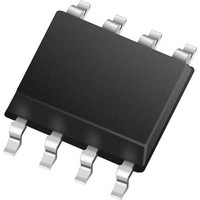
MCP79412-I/ST Microchip Technology, MCP79412-I/ST Datasheet - Page 16

MCP79412-I/ST
Manufacturer Part Number
MCP79412-I/ST
Description
Real Time Clock I2C GP RTCC 1Kb EE 64B SRAM EUI-64
Manufacturer
Microchip Technology
Series
-r
Type
Clock/Calendarr
Datasheet
1.MCP79412-ISN.pdf
(40 pages)
Specifications of MCP79412-I/ST
Function
Clock/Calendar
Rtc Memory Size
64 Byte
Maximum Operating Temperature
+ 85 C
Minimum Operating Temperature
- 40 C
Rtc Bus Interface
I2C
Supply Current
1 uA
Features
Alarm, Leap Year, NVSRAM, Square Wave Output, Unique ID
Memory Size
64B
Time Format
HH:MM:SS (12/24 hr)
Date Format
YY-MM-DD-dd
Interface
I²C
Voltage - Supply
1.8 V ~ 5.5 V
Voltage - Supply, Battery
1.3 V ~ 5.5 V
Operating Temperature
-40°C ~ 85°C
Mounting Type
Surface Mount
Package / Case
8-TSSOP (0.173", 4.40mm Width)
Lead Free Status / RoHS Status
Lead free / RoHS Compliant
MCP7941X
4.2.6
The MCP7941X has been designed to operate with a
standard 32.768 kHz tuning fork crystal. The on-board
oscillator has been characterized to operate with a
crystal of maximum ESR of 70K Ohms.
Crystals with a comparable specification are also suit-
able for use with the MCP7941X.
The table below is given as design guidance and a
starting point for crystal and capacitor selection.
EQUATION 4-1:
DS22266C-page 16
Micro Crystal
Citizen
Please work with your crystal vendor.
Manufacturer
CRYSTAL SPECS
C
load
=
-----------------------------
CX2
CX2 CX1
CM7V-T1A
CM200S-32.768KDZB-UT
+
CX1
Part Number
+
C
stray
7pF
6pF
Capacitance
Crystal
The following must also be taken into consideration:
• Pin capacitance (to be included in Cx2 and Cx1)
• Stray Board Capacitance
The recommended board layout for the oscillator area
is shown in
crystal and the load capacitors. In this example, C2 is
CX1, C3 is CX2 and the crystal is designated as Y1.
FIGURE 4-3:
Gerber files are available from
rtcc.
It is required that the final application should be tested
with the chosen crystal and capacitor combinations
across all operating and environmental conditions.
Please also consult with the crystal specification to
observe correct handling and reflow conditions and for
information on ideal capacitor values.
For more information please see the RTCC Best Prac-
tices AN1365.
10pF
10pF
Figure
CX1 Value
2010-2011 Microchip Technology Inc.
4-3. This actual board shows the
BOARD LAYOUT
12pF
8 pF
www/microchip.com/
CX2 Value


