NB100LVEP222FA ON Semiconductor, NB100LVEP222FA Datasheet

Clock Drivers & Distribution 2.5/3.3V 1:15 Diff

NB100LVEP222FA

Manufacturer Part Number
NB100LVEP222FA
Description
Clock Drivers & Distribution 2.5/3.3V 1:15 Diff
Manufacturer
ON Semiconductor
Type
ECL, PECLr
Datasheet

Specifications of NB100LVEP222FA

Minimum Operating Temperature
- 40 C
Mounting Style
SMD/SMT
Multiply / Divide Factor
2:1
Number Of Clock Inputs
2
Output Logic Level
ECL
Supply Voltage (max)
+/- 3.8 V
Supply Voltage (min)
+/- 2.375 V
Maximum Operating Temperature
+ 85 C
Package / Case
LQFP-52 Exposed Pad
Lead Free Status / RoHS Status
Lead free / RoHS Compliant

Available stocks

Company
Part Number
Manufacturer
Quantity
Price
Part Number:
NB100LVEP222FAG
Manufacturer:
ON Semiconductor
Quantity:
10 000
Part Number:
NB100LVEP222FAG
Manufacturer:
ON/安森美
Quantity:
20 000
Part Number:
NB100LVEP222FAR2
Manufacturer:
ON Semiconductor
Quantity:
10 000
Part Number:
NB100LVEP222FARG
Manufacturer:
ON Semiconductor
Quantity:
10 000
2.5 V/3.3 V 1:15 Differential
ECL/PECL ÷1/÷2 Clock Driver
fanout buffer designed with clock distribution in mind. The
LVECL/LVPECL input signal pairs can be used in a differential
configuration or single−ended (with V
and connected to the unused input of a pair). Either of two fully
differential clock inputs may be selected. Each of the four output
banks of 2, 3, 4, and 6 differential pairs may be independently
configured to fanout 1X or 1/2X of the input frequency. When the
output banks are configured with the B1 mode, data can also be
distributed. The LVEP222 specifically guarantees low output to output
skew. Optimal design, layout, and processing minimize skew within a
device and from lot to lot. This device is an improved version of the
MC100LVE222 with higher speed capability and reduced skew.
Any changes may cause indeterminate output states requiring an MR
pulse to resynchronize any 1/2X outputs (See Figure 4). Unused
output pairs should be left unterminated (open) to reduce power and
switching noise.
from a positive V
LVEP222 to be used for high performance clock distribution in
+2.5/3.3 V systems. In a PECL environment series or Thevenin line,
terminations are typically used as they require no additional power
supplies. For more information on using PECL, designers should refer
to Application Note AN1406/D. For a SPICE model, refer to
Application Note AN1560/D.
this device only. For single−ended LVPECL input conditions, the
unused differential input is connected to V
voltage. V
V
or sinking to 0.5 mA. When not used, V
Single−ended CLK input operation is limited to a V
LVPECL mode, or V
Features
*For additional information on our Pb−Free strategy and soldering details, please
© Semiconductor Components Industries, LLC, 2010
February, 2010− Rev. 12
download the ON Semiconductor Soldering and Mounting Techniques
Reference Manual, SOLDERRM/D.
NB100LVEP222
BB
The NB100LVEP222 is a low skew 1:15 differential ÷1/÷2 ECL
The fsel pins and CLK_Sel pin are asynchronous control inputs.
The NB100LVEP222, as with most ECL devices, can be operated
The V
V
NECL Mode Operating Range:
V
20 ps Output−to−Output Skew
85 ps Part−to−Part Skew
Selectable 1x or 1/2x Frequency Outputs
LVPECL Mode Operating Range:
Internal Input Pulldown Resistors
Performance Upgrade to ON Semiconductor’s MC100LVE222
V
Pb−Free Packages are Available*
CC
CC
BB
and V
/V
/V
Output
BB
CC0
CC0
BB
CC
pin, an internally generated voltage supply, is available to
may also rebias AC coupled inputs. When used, decouple
/V
= 0 V with V
= 2.375 V to 3.8 V with V
CC0
CC
/V
via a 0.01 mF capacitor and limit current sourcing
EE
CC0
v −3.0 V in NECL mode.
EE
supply in LVPECL mode. This allows the
= −2.375 V to −3.8 V
BB
EE
BB
output reference bypassed
= 0 V
BB
as a switching reference
should be left open.
CC
/V
CC0
≥ 3.0 V in
1
See detailed ordering and shipping information in the package
dimensions section on page 11 of this data sheet.
*For additional marking information, refer to
Application Note AND8002/D.
CASE 485M
CASE 848H
MN SUFFIX
FA SUFFIX
LQFP−52
QFN−52
A
WL
YY
WW
G
ORDERING INFORMATION
1
52
http://onsemi.com
= Assembly Location
= Wafer Lot
= Year
= Work Week
= Pb−Free Package
Publication Order Number:
1
1
NB100LVEP222/D
52
DIAGRAMS*
52
AWLYYWWG
MARKING
AWLYYWWG
LVEP222
LVEP222
NB100
NB100

Related parts for NB100LVEP222FA

NB100LVEP222FA Summary of contents

Page 1

... V Output BB • Pb−Free Packages are Available* *For additional information on our Pb−Free strategy and soldering details, please download the ON Semiconductor Soldering and Mounting Techniques Reference Manual, SOLDERRM/D. © Semiconductor Components Industries, LLC, 2010 February, 2010− Rev. 12 output reference bypassed switching reference BB should be left open ...

Page 2

V CC0 41 Qb2 42 Qb2 43 Qb1 44 Qb1 45 Qb0 46 Qb0 47 V CC0 Qa1 48 Qa1 49 Qa0 50 Qa0 CC0 1 2 All and V ...

Page 3

VCC fsela 3 fselb 4 5 CLK0 CLK0 6 7 CLK_SEL CLK1 8 CLK1 9 10 VBB fselc 11 12 fseld 13 VEE Table 1. PIN DESCRIPTION PIN FUNCTION CLK0*, CLK0** ECL Differential Input Clock CLK1*, CLK1** ...

Page 4

MR CLK0 CLK0 CLK1 CLK1 CLK_SEL V BB fsela fselb CC0 fselc V EE fseld CLK MR Q (B2) Q (B1) ÷1 ÷2 Figure 3. Logic Diagram Figure 4. Master Reset (MR) Timing Diagram http://onsemi.com 4 Qa0:1 ...

Page 5

Table 3. ATTRIBUTES Internal Input Pulldown Resistor Internal Input Pullup Resistor ESD Protection Moisture Sensitivity, Indefinite Time Out of Drypack (Note 1) Flammability Rating Transistor Count Meets or Exceeds JEDEC Spec EIA/JESD78 IC Latchup Test 1. For additional information, refer ...

Page 6

Table 5. LVPECL DC CHARACTERISTICS Symbol Characteristic I Power Supply Current EE V Output HIGH Voltage (Note Output LOW Voltage (Note Input HIGH Voltage (Single−Ended) IH (Note 4) V Input LOW Voltage (Single−Ended) IL ...

Page 7

Table 7. LVNECL DC CHARACTERISTICS Symbol Characteristic I Power Supply Current EE V Output HIGH Voltage (Note 11 Output LOW Voltage (Note 11 Input HIGH Voltage (Single−Ended Input LOW Voltage (Single−Ended Output ...

Page 8

Table 8. AC CHARACTERISTICS V (Note 14) Symbol Characteristic V Differential Output Voltage Opp (Figure 5) t Propagation Delay (Differential Configuration) PLH t PHL t Within−Device Skew (Note 15) skew (÷1 Mode) − Within−Device Skew (Note 15) skew ...

Page 9

RMS JITTER 300 200 0.1 0.5 Figure 5. Output Voltage (V ) versus Input Frequency and Random Clock Jitter (t OPP V PP Figure 6. LVPECL Differential Input Levels Q AMP (÷ ...

Page 10

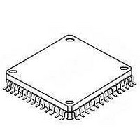
Using the thermally enhanced package of the NB100LVEP222 The NB100LVEP222 uses a thermally enhanced 52−lead LQFP package. The package is molded so that a portion of the leadframe is exposed at the surface of the package bottom side. This exposed ...

Page 11

... AND8066/D − Interfacing with ECLinPS AND8090/D − AC Characteristics of ECL Devices ORDERING INFORMATION Device NB100LVEP222FA NB100LVEP222FAG NB100LVEP222FAR2 NB100LVEP222FARG NB100LVEP222MNG NB100LVEP222MNR2G †For information on tape and reel specifications, including part orientation and tape sizes, please refer to our Tape and Reel Packaging Specifications Brochure, BRD8011/ ...

Page 12

M M/2 AJ −Z− −X− A/2 A DETAIL AH −T− SEATING PLANE 0.08 (0.003 EXPOSED PAD VIEW AG−AG ...

Page 13

... Opportunity/Affirmative Action Employer. This literature is subject to all applicable copyright laws and is not for resale in any manner. PUBLICATION ORDERING INFORMATION LITERATURE FULFILLMENT: Literature Distribution Center for ON Semiconductor P.O. Box 5163, Denver, Colorado 80217 USA Phone: 303−675−2175 or 800−344−3860 Toll Free USA/Canada Fax: 303− ...

Related keywords