140-0000-964 JOHNSON/EMERSON, 140-0000-964 Datasheet - Page 3
140-0000-964
Manufacturer Part Number
140-0000-964
Description
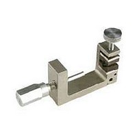
Cable Clamp Insert
Manufacturer
JOHNSON/EMERSON
Datasheet
1.140-0000-964.pdf
(3 pages)
Specifications of 140-0000-964
Peak Reflow Compatible (260 C)
Yes
Leaded Process Compatible
Yes
For Use With
SMK 2.92mm Coaxial Connectors
Lead Free Status / RoHS Status
Lead free / RoHS Compliant


SMK - 50 Ohm Connectors (2.92mm)
INCHES (MILLIMETERS)
SMK Solder Type Straight Plugs For Semi-rigid Cable
6
1
2
3
4
5
•
COUPLING NUT
Johnson Components
CUSTOMER DRAWINGS AVAILABLE UPON REQUEST
BEAD ASSEMBLY TOOL
.000 - .005 RECESSION
BEAD TO BODY
BODY
™
• P.O. Box 1732 • Waseca, MN 56093-0832 • 1-800-247-8256 • Fax: 507-833-6287 • www.johnsoncomponents.com
BEAD
SEAL RING
CABLE SOLDERING VISE
BEAD
CONTACT
VISE STOP
PLUNGER
2
1
2
3
3
4
5
6
Identify connector parts (5 piece parts) and tools (5 tools.)
Strip cable jacket and dielectric to dimension shown.
Place center contact onto center conductor. Slide con-
tact soldering tool onto contact. Clamp the cable con-
tact and tool into cable soldering vise and solder con-
tact to center conductor. High temperature solder,
such as 95/5 Sn/Ag is recommended so that contact
solder joint remains stable during body soldering op-
eration. Solder paste is recommended for the contact
solder joint to minimize excess solder. The assembled
dimension should be as shown.
Remove excess solder from contact with a sharp blade
and clean contact. Check for presence of excess sol-
der by sliding body soldering tool over the contact. Re-
move soldering tool.
Place connector nut and body on cable. Place con-
nector body soldering tool over contact and thread the
coupling nut and connector body firmly to the tool. Place
cable subassembly into cable soldering vise. Clamp
cable and soldering tool securely to insure the cable
dielectric expansion will not disturb the cable in the vise
during soldering. Place hot soldering iron on the con-
nector body sleeve and apply solder from the opposite
side. A low temp solder, such as 60/40 Sn/Pb is rec-
ommended for the body solder joint. Allow the soldered
joint to cool and remove from fixture. Check contact
location to the body. The best electrical results are
achieved when the contact location is within a toler-
ance of .060 +/- .001.
Place bead onto neck portion of the tool. Thread Bead
Assembly tool firmly into the coupling nut. Push the
tool's plunger between your thumb and fingers to as-
semble the bead. Check bead location. Assemble seal
ring onto body.
Contact Soldering Tool
Semi-Rigid Cable Vise
Body Soldering Tool
Cable Clamp Insert
Bead Assy. Tool
TOOL
Vise Stop
VISE STOP
CABLE SOLDERING VISE
P/N 140-0000-962
145-0693-001/002
(FOR .086 SEMI-RIGID)
140-0000-962
140-0000-968
140-0000-957
140-0000-960
140-0000-958
140-0000-964
ASSEMBLY
BEAD
TOOL
145-0694-001/002
(FOR .141 SEMI-RIGID)
140-0000-962
140-0000-968
140-0000-957
140-0000-961
140-0000-959
140-0000-965