72-7935 TENMA, 72-7935 Datasheet
72-7935
Specifications of 72-7935


72-7935 Summary of contents
Page 1
...
Page 2
... Model 72-7935: OPERATING MANUAL Table of Contents (1) Table of Contents Title Overview Inspection Safety Information Rules For Safe Operation International Electrical Symbols The Meter Structure Functional Buttons Measurement Operation A. DC Voltage Measurement B. AC Voltage Measurement C. Measuring Resistance D. Frequency and Duty Cycle Measurement E. Measuring Diodes & Continuity F ...
Page 3
... Title Sleep Mode General Specifications Accuracy Specifications A. DC Voltage B. AC Voltage C. Resistance Test D. Frequency E. Duty Cycle F. Diodes and Continuity Test G. Capacitance Maintenance A. General Service B. Replacing the Battery Model 72-7935: OPERATING MANUAL Table of Contents (2) 2 Page ...
Page 4
... To avoid the risk of injury from electric shock, read the “Safety Information” and “Rules For Safe Operation” carefully before using the meter. The Digital Multimeter Model 72-7935 (hereafter referred to as the meter highly reliable handheld measuring instrument featuring a variety of functions in a compact design ...
Page 5
... This meter includes the following items: Item Description 1 English Operating Manual 2 Built-In Test Lead 3 Vinyl Holder 4 3V Button Battery (CR2032) In the event items missing or damaded, please contact your dealer immediately. Model 72-7935: OPERATING MANUAL Unpacking Inspection 4 Qty 1 piece 1 pair 1 piece 1 piece ...
Page 6
... Model 72-7935: OPERATING MANUAL Safety Information Safety Information This Meter complies with the standards IEC61010: in pollution degree 2, overvoltage category (CAT. II 300V) and double insulation. CAT. II: Local level, appliance, PORTABLE EQUIPMENT etc., with smaller transient voltage overvoltages than CAT. III Use the Meter only as specified in this operating manual, otherwise the protection provided by the Meter may be impaired ...
Page 7
... Do not apply more than the rated voltage, as marked on the Meter, between the terminals or between any terminal and grounding. l The rotary switch should be placed in the desired position prior to connecting leads. This position should not be changed while leads are connected. Model 72-7935: OPERATING MANUAL Rules For Safe Operation (1) 6 ...
Page 8
... Model 72-7935: OPERATING MANUAL Rules For Safe Operation (2) l When using the Meter at an effective voltage over 60V DC 30V rms AC, special care should be taken for there is danger of electric shock. l Use the proper terminals, function, and range for your measurements not use or store the Meter in an environment of high temperature, humidity, explosive, inflammable and strong magnetic field ...
Page 9
... The Meter is suitable for indoor use only. l Turn the Meter power off when it is not in use and take out the battery when not using for a long time. l Periodically check the battery for leaks, a leaking battery will damage the meter. Model 72-7935: OPERATING MANUAL Rules For Safe Operation (3) 8 ...
Page 10
... Model 72-7935: OPERATING MANUAL International Electrical Symbols International Electrical Symbols Low Battery AC (Alternating Current) Capacitance Double Insulated Warning. Refer to the Operating Manual Conforms to Standards of European Union Ground DC (Direct Current) Diode Continuity Test Fuse 9 ...
Page 11
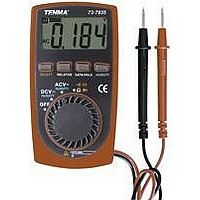
... The Meter Structure (see figure 1) 1. LCD Display 2. SELECT Button 3. RELATIVE Mode Button 4. DATA HOLD Button 5. Hz/DUTY Button 6. Rotary Switch 7. Black Test Lead 8. Red Test Lead Model 72-7935: OPERATING MANUAL The Meter Structure figure ...
Page 12
... Model 72-7935: OPERATING MANUAL Functional Buttons Functional Buttons Button Operation Performed Press SELECT to switch between resistance, capacitance, continuity buzzer and SELECT diode measurement modes; the Meter beeps. Resistance measurement is default. Press RELATIVE to enter and exit the REL mode in any measuring mode except RELATIVE in frequency/duty cycle ...
Page 13
... Make sure the Sleep Mode is not on if there is no display on the LCD after turning on the Meter. l Make sure the Low Battery Display occour. l Pay extra attention to the of the Meter before carrying out measeurement. Model 72-7935: OPERATING MANUAL Measurement Operation(1) is not on, otherwise false readings may symbol which is located besides the input terminals 12 ...
Page 14
... Model 72-7935: OPERATING MANUAL Measurement Operation( Voltage Measurement (see figure 2) Red Black ( figure 2) 13 ...
Page 15
... The measured value shows on the display. Note l The LCD displays the negative reading when the test lead connection is reversed. When DC voltage measurement has been completed, disconnect the connection l between the testing leads and the circuit under test. Model 72-7935: OPERATING MANUAL Measurement Operation (3) 3 range. 14 ...
Page 16
... Model 72-7935: OPERATING MANUAL Measurement Operation ( Voltage Measurement (see figure 2 with dotted line) Warning To avoid harm to you or damage to the Meter from electric shock, please do not attempt to measure voltages higher than 300V although readings may be obtained and take extra care when measuring high voltage. ...
Page 17
... C. Measuring Resistance (see figure 3) Hz/Duty Model 72-7935: OPERATING MANUAL Measurement Operation (5) Red Black ( figure 3) 16 ...
Page 18
... Model 72-7935: OPERATING MANUAL Measurement Operation(6) Warning To avoid damage to the Meter or to the devices under test, disconnect circuit power and discharge all the high-voltage capacitors before measuring resistance. To measure resistance, connect the Meter as follows: 1. Set the rotary switch to 2. Connect the test leads across with the object being measured. ...
Page 19
... For high resistance (> normally requires several seconds to obtain a stable reading. l When there is no input, for example in open circuit condition, the Meter displays “OL”. l When resistance measurement has been completed, disconnect the connection between the leads and the circuit under test. Model 72-7935: OPERATING MANUAL Measurement Operation(7) 18 ...
Page 20
... Model 72-7935: OPERATING MANUAL Measurement Operation(8) D. Frequency and Duty Cycle Measurement (see figure 3 with dotted line) Warning To avoid harm to you or damage to the Meter, do not attempt to measure voltages higher than 60V DC or 30V rms AC although readings may be obtained. The testing resolution may vary from the inputted frequency and waveform, the Meter resolution is based on the sine wave ...
Page 21
... The diode test sends a current through the semiconductor junction, and then measures the voltage drop across the junction. A good silicon junction drops between 0.5V and 0.8V. To test out a diode out of a circuit, connect the Meter as follows: 1. Set the rotary switch to Model 72-7935: OPERATING MANUAL Measurement Operation(9) range. 20 ...
Page 22
... Model 72-7935: OPERATING MANUAL Measurement Operation(10) 2. Press SELECT button to select diode test. 3. For forward voltage drop readings on any semiconductor component, place the red test lead on the component’s anode and place the black test lead on the component’s cathode. The LCD displays the nearest value of diode forward voltage drop. ...
Page 23
... The buzzer sounds continuously if the resistance of a circuit under test is less than 100 . The LCD displays the resistance value of a circuit under test. Note l When continuity testing has been completed, disconnect the connection between the leads and the circuit under test. Model 72-7935: OPERATING MANUAL Measurement Operation(11) range. 22 ...
Page 24
... Model 72-7935: OPERATING MANUAL Measurement Operation(12) F. Capacitance Measurement (see figure 3 with dotted line) Warning To avoid damage to the Meter or to the equipment under test, disconnect the tested circuit power when measuring on line capacitors and discharge all high- voltage capacitors before measuring capacitance. ...
Page 25
... For testing the capacitor with polarity, connect the red test lead to anode & black test lead to cathode l For measuring capacitance higher than 100 F, it normally requires several secends to obtain a stable reading. l When capacitance measurement has been completed, disconnect the connection between the leads and the circuit under test. Model 72-7935: OPERATING MANUAL Measurement Operation(13) 24 ...
Page 26
... Model 72-7935: OPERATING MANUAL Sleep Mode To preserve battery life, the meter enters sleep mode after 15 minutes of inactivity. In this mode, the battery current draw is approximately 10 A. The meter can be reactivated by pressing the SELECT button. Sleep Mode 25 ...
Page 27
... Negative reading: Display “ l Overloading: Display “OL”. l Dimensions (HxWxL): 4.25 x 2. Weight: Approx.4.4OE (battery and test lead included). l Safety/Compliances: IEC61010 CAT II 300V overvoltage and double insulation standard. l Certificate: Model 72-7935: OPERATING MANUAL General Specifications C~40 C(32 F~104 F), Relative Humidity ...
Page 28
... Model 72-7935: OPERATING MANUAL Accuracy Specifications(1) Accuracy Specifications Accuracy: (a% reading + b digits), guarantee for 1 year. 0 Operating temperature Relative humidity: <75%. Temperature coefficient: 0.1 x (specified accuracy ...
Page 29
... A. DC Voltage Range Resolution Accuracy Overload Protection (0.8%+3) 400mV 0.1mV 4V 1mV (0.8%+1) 40V 10mV 300V 100mV Model 72-7935: OPERATING MANUAL Accuracy Specifications(2) 300V DC Input Impedance: 10M 300V AC. 28 Remarks ...
Page 30
... Model 72-7935: OPERATING MANUAL Accuracy Specifications( Voltage Range Resolution Accuracy Overload Protection 4V 1mV (1.2%+3) 40V 10mV 300V 100mV Remarks l Input Impedance: 10M . l Frequency response: 300V DC 40Hz~400Hz. 300V AC. l Display effective value of sine wave (mean value response). 29 ...
Page 31
... C. Resistance Test Range Resolution Accuracy Overload Protection (1.2%+2) 400 0 (1%+2) 40k 10 400k 100 (1.2%+ (1.5%+2) 40M 10k Model 72-7935: OPERATING MANUAL Accuracy Specifications(4) Open circuit voltage: 250V AC approx. 0.45V 30 Remarks ...
Page 32
... Model 72-7935: OPERATING MANUAL Accuracy Specifications(5) D. Frequency Range Resolution Accuracy Overload Protection 99.99Hz 0.01Hz 999.9Hz 0.1Hz (0.5%+3) 9.999kHz 0.001kHz 99.99kHz 0.01kHz Remarks l The inputted voltage is sine wave l When 10Hz ~10kHz: 250V AC 1V rms l When 10kHz~100kHz: 30V rms. 31 ...
Page 33
... AC 99.9% F. Diodes and Continuity Test Function Range Resolution Diode 1mV Continuity 0.1 Buzzer Model 72-7935: OPERATING MANUAL Accuracy Specifications(6) Remarks l Press Hz/DUTY button at ACV DCV range to select Duty Cycle measurement mode. l Reading is only for reference, Input Protection Open circuit voltage approx.1.5V l Open circuit voltage approx ...
Page 34
... Model 72-7935: OPERATING MANUAL Accuracy Specifications(7) G. Capacitance Range Resolution Accuracy Overload Protection 4nF 0.001nF 40nF 0.01nF 400nF 0.1nF (4%+ 0.001 0.01 F (5%+10) 200 F 0.1 F Remarks Reading is only for reference l Open circuit voltage: around 0.45V 250V AC l Measuring under Relative mode. When the tested capacitor is ...
Page 35
... This section provides basic maintenance information including battery and fuse replacement instruction. Warning Do not attempt to repair or service your Meter unless you are qualified and have the relevant calibration, performance test, and service information. To avoid electric shock or damage to the Meter allow water inside the case. Model 72-7935: OPERATING MANUAL Maintenance(1) 34 ...
Page 36
... Model 72-7935: OPERATING MANUAL A. General Service l Periodically wipe the case with damp cloth and mild detergent. Do not use chemical solvent clean the terminals with cotton bar with detergent, as dirt or moisture in the terminals can affect readings. l Clean terminals with cotton ball with detergent, as dirt or moisture in the terminals can affect readings ...
Page 37
... B. Replacing the Battery (see figure 4) Model 72-7935: OPERATING MANUAL Maintenance(3) SCREW (figure 4) 36 ...
Page 38
... Model 72-7935: OPERATING MANUAL Warning To avoid false readings, which could lead to possible electric shock or personal injury, replace the battery as soon as the battery indicator To replace battery: 1. Disconnect the connection between the leads and the circuit under test. 2. Turn the Meter OFF 3. Remove the screw from the case bottom; separate the case bottom from the case top ...
Page 39
... Copyright 2005 Tenma Test Equipment. All rights reserved. Tenma Test Equipment 405 S. Pioneer Blvd. Springboro,Ohio 45066 www.tenma.com Model 72-7935: OPERATING MANUAL 38 ...