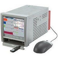
ALITE EUROTHERM CONTROLS, ALITE Datasheet - Page 5

ALITE
Manufacturer Part Number
ALITE
Description
Auditor Trail Option Software
Manufacturer
EUROTHERM CONTROLS
Datasheet
1.MODBUS.pdf
(8 pages)
Specifications of ALITE
Accessory Type
Audit Trial Option Software
For Use With
Eurotherm 6000 Series Graphical Paperless Recorders
Lead Free Status / RoHS Status
na
y
x
2 Option
Boards
2 Option
Boards
2 Option
Boards
2 Option
Boards
1
Voltages generated by
various currents for
R = 100
20 mA
0 mA
4 mA
Event input Number
2
1 2 3 4 5 6 7 8 9 10 11 12 13 14 15 16 17 18 19 20 21 22
1 2 3 4 5 6 C
1
Contact closure inputs
3
1, 7, 13, 19, 25,
V+ V- I V+ V- I
2
100
0.4 V
2.0 V
and R =250
31, 37, 43
Channels
0 V
4
1 2 3 4 5 6 7 8 9 10 11 12 13 14 15 16 17 18 19 20 21 22
nc c no
Rly 1
Rly 1
3
1 2 3 4 5 6 7 8 9 10 11 12 13 14 15 16 17 18 19 20 21 22
Relay 1
1 2 3 4 5 6 7 8 9 10 11 12 13 14 15 16 17 18 19 20 21 22
c
1 2 3 4 5 6 7 8 9 10 11 12 13 14 15 16 17 18 19 20 21 22
c
V+ –
Channel
nc
no
5
250
1.0 V
5.0V
4
Max number of boards = 4 for small frame or 9 for large frame
0 V
1
Rly 2
Rly 2
2, 8, 14, 20, 26,
6
5
c
c
I+
Channels
32, 38, 44
no
nc c no
nc
Relay 2
6
C
Transmitter
V+ V-
Channel input
terminal panel
-
V+ –
Recorder rear
Channel
7
R
Rly 3
Rly 3
c
c
2
3, 9, 15, 21, 27,
V+ V- I
8
Channels
33, 39, 45
nc c no
nc c nc
no c no
I+
Relay 3
+
9 10 11 12 13 14 15 16 17 18 19 20 21 22
Four normally closed relays
Four normally open relays
Three changeover relays
Rly 4
Rly 4
I
junction
Long terminal cover
Cold
+0.8 to -30 V
R (minimum spec) = 1.4W,
shown, for clarity.
Only one channel
+2 to +30 V
1 2 3 4 5 6 C
User 0V
4, 10, 16, 22, 28,
V+ V- I V+ V- I V+ V- I
–
1
Behaviour undefined for
Channels
34, 40, 46
Transmitter Power Supply
+0.8 < Vin < +2 V
Event input Number
2
V+ –
Channel
+
nc c no
Rly 1
Rly 1
Relay 1
c
c
3
1
User terminal block
5, 11, 17, 23, 29,
Voltage inputs
no
I+
nc
4
Channels
35, 41, 47
–
Rly 2
Rly 2
PCB
c
c
5
V+ –
Channel
Other transmitters
nc c no
nc
no
Relay 2
+
6
2
6, 12, 18, 24, 30,
I+
36, 42, 48
Channels
C
–
1%.
Rly 3
Rly 3
Input 6 shown;
inputs 1 to 5 identical
c
c
power off/alarm stat e
nc c no
nc c nc
no c no
c
Relay 3
Contacts shown in
+
Rly 4
Rly 4
Voltage
+
outputs
V+ –
NO
-
I+
NC
V


