85134F AGILENT TECHNOLOGIES, 85134F Datasheet
85134F
Specifications of 85134F


85134F Summary of contents
Page 1
... Operating and Service Manual Agilent Technologies 85134E/F/H NMD-2.4 mm -f- to 3.5 mm 85135E/F NMD-2 Test Port Return Cables Agilent Part Number: 85134-90001 Print Date: February 2008 Supersedes: October 2007 © Copyright 1988, 2006 - 2008 Agilent Technologies, Inc. All rights reserved. and Flexible Printed in USA ...
Page 2
... FAR 52.227-19 (June 1987) or any equivalent agency regulation or contract clause. Use, duplication or disclosure of Software is subject to Agilent Technologies’ standard commercial license terms, and non-DOD Departments and Agencies of the U.S. Government will receive no greater than Restricted Rights as defined in FAR 52.227-19(c)(1-2) (June 1987). U.S. Government users will receive no greater than Limited Rights as defined in FAR 52 ...
Page 3
CAUTION The cable center conductor is fragile and will be seriously damaged if the cable is stretched, bent too tightly, or bent too often. Cables break when the bend radius is too small—less than 2.5” (6 cm) for 1.85 mm ...
Page 4
Printing Copies of Documentation from the Web To print copies of documentation from the Web, download the PDF file from the Agilent web site: • http://www.agilent.com. • Enter the document’s part number (located on the title page) in ...
Page 5
... General Information The Cable Sets . . . . . . . . . . . . . . . . . . . . . . . . . . . . . . . . . . . . . . . . . . . . . . . . . . . . . . . . . . . . . . . . . . . . . . 1-2 85134E and 85135E . . . . . . . . . . . . . . . . . . . . . . . . . . . . . . . . . . . . . . . . . . . . . . . . . . . . . . . . . . . . . . . . 1-2 85134F and 85135F . . . . . . . . . . . . . . . . . . . . . . . . . . . . . . . . . . . . . . . . . . . . . . . . . . . . . . . . . . . . . . . . 1-2 85134H . . . . . . . . . . . . . . . . . . . . . . . . . . . . . . . . . . . . . . . . . . . . . . . . . . . . . . . . . . . . . . . . . . . . . . . . . . 1-2 Connector Designators . . . . . . . . . . . . . . . . . . . . . . . . . . . . . . . . . . . . . . . . . . . . . . . . . . . . . . . . . . . . . . 1-2 Clarifying the Terminology of a Connector Interface . . . . . . . . . . . . . . . . . . . . . . . . . . . . . . . . . . . . . . 1-3 Incoming Inspection 1-3 Preventive Maintenance . . . . . . . . . . . . . . . . . . . . . . . . . . . . . . . . . . . . . . . . . . . . . . . . . . . . . . . . . . . . . . 1-4 Replaceable Parts 1-4 2. Specifications Environmental Requirements . . . . . . . . . . . . . . . . . . . . . . . . . . . . . . . . . . . . . . . . . . . . . . . . . . . . . . . . . 2-2 Electrical Specifications 2-2 Supplemental Characteristics ...
Page 6
Contents 2 85134E/F/H & 85135E/F ...
Page 7
General Information 85134E/F/H & 85135E/F 1-1 ...
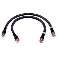
Page 8
... Figure 1-1. Figure 1-1 Cable Configurations 85134H The 85134H set contains a single cable – the -f- to -m- cable from the 85134F cable set shorter than the 85134E and 85135E single cables. See Connector Designators NMD Connectors NMD denotes a connector that has larger than standard coupling threads for greater stability ...
Page 9
DUT). PSC Connectors PSC denotes a precision slotless connector. Precision slotless connectors are metrology grade connectors that have better electrical performance, better repeatability, and are more durable than slotted connectors. Clarifying the ...
Page 10
General Information Preventive Maintenance • the model number and serial number of the cable set • the part number and serial number of the device • the type of service required • a detailed description of the problem Preventive Maintenance ...
Page 11
Specifications 85134E/F/H & 85135E/F 2-1 ...
Page 12
... Operation Storage Electrical Specifications Table 2-2 Electrical Specifications Cable SWR Return Loss (dB) ≤1.38 ≥15.94 85134E 85134F 85134H ≤1.3 ≥17.7 85135E 85135F frequency in GHz. b. Center conductor shoulder behind outer conductor mating plane. 2-2 Limits +20 °C to +26 °C (+68 °F to +79 °F) −40 °C to +75 °C (−40 °F to +167 °F) < ...
Page 13
... GHz. b. With a 90°, 2.5-inch bend radius. Table 2-3 Supplemental Characteristics ( Cable Set Number Test Set End Connector Type of Cables 85134E 1 NMD-2.4 mm -f- Slotted 85134F 2 NMD-2.4 mm -f- Slotted 85134H 1 NMD-2.4 mm -f- Slotted 85135E 1 NMD-2.4 mm -f- Slotted 85135F 2 NMD-2.4 mm -f- Slotted ...
Page 14
Specifications Supplemental Characteristics gage. Figure 2-1 Connector Center-Conductor Pin Depth Table 2-3 Supplemental Characteristics ( Precision Connector mm NMD-2.4 mm -f- -0.0000 to -0.056 NMD-3.5 mm -m- -0.0025 to -0.013 PSC-3 -0.005 to -0.021 ...
Page 15
Use, Maintenance, and Care of the Cables 85134E/F/H & 85135E/F 3-1 ...
Page 16
Use, Maintenance, and Care of the Cables Electrostatic Discharge Electrostatic Discharge Protection against ESD (electrostatic discharge) is essential while connecting, inspecting, or cleaning connectors attached to a static-sensitive circuit (such as those found in test sets). Static electricity can build ...
Page 17
Visual Inspection Visual inspection and, if necessary, cleaning should be done every time a connection is made. Metal particles from the connector threads may fall onto the mating plane surface of the connector when it is disconnected. One connection made ...
Page 18
Use, Maintenance, and Care of the Cables Precision Slotless Connectors (3.5 mm) Precision Slotless Connectors (3.5 mm) The female 3.5 mm connectors in the cable sets are metrology-grade, precision slotless connectors (PSC). Precision slotless connectors are used to improve accuracy. ...
Page 19
Cleaning Connectors Clean connectors are essential for ensuring the integrity of RF and microwave coaxial connections. 1. Use Compressed Air or Nitrogen WARNING Always use protective eyewear when using compressed air or nitrogen. Use compressed air (or nitrogen) to loosen ...
Page 20
Use, Maintenance, and Care of the Cables Cleaning Connectors you reassemble or use it. 3. Clean the Mating Plane Surfaces a. Apply a small amount of isopropyl alcohol to a lint-free cleaning swab. b. Clean the center and outer conductor ...
Page 21
... Gaging Connectors The gages available from Agilent Technologies are intended for preventive maintenance and troubleshooting purposes only. (See information.) They are effective in detecting excessive center conductor protrusion or recession, and conductor damage on test cables and other accessories, DUTs, and calibration kit devices. Do not use the gages for precise pin depth measurements. ...
Page 22
Use, Maintenance, and Care of the Cables Gaging Connectors Reading the 7mm Connector Gage The gage dial is divided into increments of 0.0001 inch and major divisions of 0.001 inch (see Figure 3-2). For each revolution of the large dial, ...
Page 23
Gaging Procedures Gaging 2.4 mm, 3.5 mm, and 7 mm Connectors Always hold a connector gage by the gage barrel, below the dial indicator. NOTE This gives the best stability, and improves measurement accuracy. (Cradling the gage in your hand ...
Page 24
Use, Maintenance, and Care of the Cables Gaging Connectors All gages: For maximum accuracy, measure the connector a minimum of three times and take an average of the readings. After each measurement, rotate the gage a quarter-turn to reduce measurement ...
Page 25
Figure 3-3 Gaging 2.4 mm and 3.5 mm Connectors 85134E/F/H & 85135E/F Use, Maintenance, and Care of the Cables Gaging Connectors 3-11 ...
Page 26
Use, Maintenance, and Care of the Cables Gaging Connectors Figure 3-4 Gaging 7 mm Connectors 3-12 85134E/F/H & 85135E/F ...
Page 27
Making Connections Good connections require a skilled operator. The most common cause of measurement error is bad connections. The following procedures illustrate how to make good connections. How to Make a Connection Preliminary Connection 1. Ground yourself and all devices. ...
Page 28
Use, Maintenance, and Care of the Cables Making Connections 7. Push the connectors straight together. Do not twist or screw the connectors together. 8. Engage the connector nut (of the connector with the retracted sleeve) over the threads of the ...
Page 29
Figure 3-5 Wrench Positions 2. Hold the torque wrench lightly, at the end of the handle only (beyond the groove). See Figure 3-6. Figure 3-6 Using the Torque Wrench 3. Apply downward force perpendicular to the wrench handle. This applies ...
Page 30
Use, Maintenance, and Care of the Cables Handling and Storage connector to be sure it will not damage the 3.5 mm connector. Use only a 90 N-cm (8 in-lb) torque wrench on any connection involving an SMA connector. How to ...
Page 31
NOTE After you perform a calibration, move the cables as little as possible. Every time you bend a cable, the phase changes slightly. 85134E/F/H & 85135E/F Use, Maintenance, and Care of the Cables Handling and Storage 3-17 ...
Page 32
Use, Maintenance, and Care of the Cables Handling and Storage 3-18 85134E/F/H & 85135E/F ...
Page 33
Replaceable Parts 85134E/F/H & 85135E/F 4-1 ...
Page 34
... Table 4-2 list the replacement part numbers for items included in the cable sets. To order a listed part, note the description, the part number, and the quantity desired. Telephone or send your order to Agilent Technologies (see page 4-3). Ordering One Cable in a Cable Set If you need only one of the cables in a cable set and don’ ...
Page 35
... Returning a Cable or Cable Set to Agilent If your cable set requires service, contact Agilent Technologies (see below). Include the following information: • your company name and address • a technical contact person within your company, and the person's complete phone number • the model number and serial number of the cable set • ...
Page 36
... Table 4-1 Replaceable Parts for the 85134E/F/H Cable Sets a Description Cables 85134E Single Cable: NMD-2.4 mm –f– to PSC-3.5 mm –f– 85134F Cables: NMD-2.4 mm –f– to NMD-3.5 mm –m– NMD-2.4 mm –f– to PSC-3.5 mm –f– 85134H Single Cable: NMD-2.4 mm –f– to NMD-3.5 mm –m– Miscellaneous ...
Page 37
Table 4-1 Replaceable Parts for the 85134E/F/H Cable Sets a Description 3.5 mm female gage set 10x Magnifying Glass 3 Ω fixed termination -m- 3 Ω fixed termination -f- 3.5 mm offset short -m- 3.5 mm ...
Page 38
Replaceable Parts Returning a Cable or Cable Set to Agilent Table 4-2 Replaceable Parts for the 85135E/F Cable Sets a Description Cables 85135E Single Cable: NMD-2.4 mm –f– to 7mm 85135F Cables: NMD-2.4 mm –f– Miscellaneous Operating ...
Page 39
Table 4-2 Replaceable Parts for the 85135E/F Cable Sets a Description Collet extractor tool 7 mm Airline (10 cm) Refer to “Clarifying the Terminology of a Connector Interface” on page 1-3 a. 85134E/F/H & 85135E/F Replaceable Parts Returning a Cable ...
Page 40
Replaceable Parts Returning a Cable or Cable Set to Agilent 4-8 85134E/F/H & 85135E/F ...
Page 41
A Connector Care Quick Reference 85134E/F/H & 85135E/F A-1 ...
Page 42
Connector Care Quick Reference Principles of Microwave Connector Care Principles of Microwave Connector Care Proper connector care and connection techniques are critical for accurate, repeatable measurements and for extending the life of your devices. Prior to making connections to the ...
Page 43
Table A-1 Connector Care Quick Reference Do Keep connectors clean Extend sleeve or connector nut Use plastic end-caps during storage Do Inspect all connectors carefully Look for metal particles, scratches, and dents Do Try compressed air first a Use isopropyl ...
Page 44
Connector Care Quick Reference Principles of Microwave Connector Care A-4 85134E/F/H & 85135E/F ...
Page 45
A , adapters, part numbers 4-4 , Agilent,contacting 4-3 alcohol, isopropyl, as cleaning solvent , altitude 2-2 , avoiding cable movement 3-16 C cable , length 2-3 , maintenance 1-4 , movement 3-16 , part numbers 4-4 cable set , ...
Page 46
Index , part numbers 4-4 gaging , connectors 3-9 , when to do 3-7 , gender, connector 1 handling 3-16 , humidity 2 incoming inspection 1-3 insertion loss , specificatons 2-2 inspection , damage 3-3 , ...
Page 47
T temperature , operating range 2-2 threads , connector 3-5 torque wrench , part number 4-4 , specifications 3- visual inspection 3 warranty, documentation -ii wrench , , , open-end 3-15 3-16 4-4 , part numbers ...