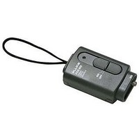
FOS-850/1300 FLUKE NETWORKS, FOS-850/1300 Datasheet - Page 5

FOS-850/1300
Manufacturer Part Number
FOS-850/1300
Description
FIBER OPTIC METER
Manufacturer
FLUKE NETWORKS
Datasheet
1.FOS-8501300.pdf
(10 pages)
Specifications of FOS-850/1300
Connector Type
Fixed ST
Operating Temperature Range
0°C To +40°C
Lead Free Status / RoHS Status
na
850 nm Calibration Adjustment
1. Set the switch on the FOM to the 850 nm
2. Connect the light source to the reference power
3. Connect the 850 nm light source to the FOM.
4. Adjust R1 for an output on the DMM of P o
5. Apply insulating varnish, such as red GLPT, to
1550 nm Calibration Adjustment
1. Set the switch on the FOM to the 1550 nm
2. Connect the light source to the reference power
3. Connect the 1550 nm light source to the FOM.
4. Adjust R3 for an output on the DMM of P o
5. Apply insulating varnish, such as red GLPT, to
At this point, the calibration adjustment is
complete.
Verifying Calibration
Follow the procedure under "Performance Tests"
earlier in this document.
Calibration Adjustments for the
FOS
Refer to the FOS drawing (Figure 2) for the
locations of components.
1. Connect the FOS to the calibrated FOM with a
2. Connect the FOM to a DMM with at least 0.1
position.
meter. Set the 850 nm light source for a power
meter reading of -10 0.05 dBm.
Record this level as P o to use in step 4.
Connect the FOM to the DMM.
±0.05 dBm.
the R1 potentiometer.
position.
meter. Set the 1550 nm light source to
-10 0.05 dBm.
Record this reading as P o to use in step 4.
Connect the FOM to the DMM.
±0.05 dBm.
the R3 potentiometer.
patch cable. Turn the FOS on and let it stabilize
for 20 minutes.
mV resolution. Turn the FOM on and set it to
the desired wavelength.
FOS-850 Plastic Case Assembly
FOS-1300 Plastic Case Assembly
FOS-850/1300 Plastic Case Assembly
Battery Door
Slide Switch Actuator
850 LED
1300 LED
3. For 850 nm calibration, adjust R21 until the
4. Apply insulating varnish, such as red GLPT, to
Parts and Accessories
Tables 3 and 4 contain replacement parts for the
FOM and FOS that are available from Fluke. Table
5 lists available accessories.
FOM Plastic Case Assembly
Battery Door
Slide Switch Actuator
PD1: Germanium Photodiode, 1 mm
ST to ST Multimode Patch Cable, 1m
ST to ST Mating Sleeve
ST to FC Patch Cable
ST to SC Patch Cable
ST to SMA Patch Cable
Table 3. Fluke Replacement Parts for the FOM
output on the DMM reads -20
1300 nm calibration, adjust R20 until the output
on the DMM reads -20
each potentiometer adjusted.
Table 4. Fluke Replacement Parts for the FOS
Table 5. Accessories for the FOM and FOS
Description
Description
Description
Calibration Adjustments for the FOS
Fiber Optic Meter/Source
0.1 mV.
0.1 mV. For
Fluke Part
Fluke Part
Fluke Part
Number
Number
617354
617388
617412
200474
200482
602755
602760
Number
617339
200474
200482
602788
617453
602810
617487
617511
616545
5


