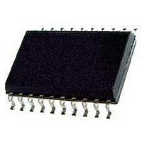
CAT522WI-T2 ON Semiconductor, CAT522WI-T2 Datasheet - Page 4

CAT522WI-T2
Manufacturer Part Number
CAT522WI-T2
Description
Digital Potentiometer ICs DPP,NV,256 taps Dual 3 wire,w/Buf
Manufacturer
ON Semiconductor
Datasheet
1.CAT522WI-T2.pdf
(15 pages)
Specifications of CAT522WI-T2
Number Of Pots
Dual
Taps Per Pot
256
Resistance
24 KOhms
Wiper Memory
Non Volatile
Digital Interface
Serial (3-Wire, Microwire)
Operating Supply Voltage
3.3 V, 5 V
Supply Current
600 uA
Mounting Style
SMD/SMT
Supply Voltage (max)
5.5 V
Supply Voltage (min)
2.7 V
Package / Case
SOIC-14
Number Of Elements
2
# Of Taps
256
Power Supply Requirement
Single
Single Supply Voltage (typ)
3.3/5V
Dual Supply Voltage (typ)
Not RequiredV
Single Supply Voltage (min)
2.7V
Single Supply Voltage (max)
5.5V
Dual Supply Voltage (min)
Not RequiredV
Dual Supply Voltage (max)
Not RequiredV
Operating Temp Range
-40C to 85C
Operating Temperature Classification
Industrial
Mounting
Surface Mount
Pin Count
14
Package Type
SOIC
Lead Free Status / RoHS Status
Lead free / RoHS Compliant
CAT522
POTENTIOMETER CHARACTERISTICS
V
AC ELECTRICAL CHARACTERISTICS
V
Notes:
(1) All timing measurements are defined at the point of signal crossing V
(2) These parameters are periodically sampled and are not 100% tested.
Doc. No. MD-2004 Rev. I
Symbol
Digital
t
t
t
t
t
t
t
t
t
t
t
t
t
t
f
Analog
t
DD
DD
Symbol
CSMIN
CSS
CSH
DIS
DIH
DO1
DO0
HZ
LZ
BUSY
PS
PROG
CLK
CLK
C
DS
TC
C
R
R
DNL
= +2.7V to +5.5V, V
INL
I
= +2.7V to +5.5V, V
OUT
H
H
L
POT
OUT
RPOT
/C
L
Parameter
Minimum CS Low Time
CS Setup Time
CS Hold Time
DI Setup Time
DI Hold Time
Output Delay to 1
Output Delay to 0
Output Delay to High-Z
Output Delay to Low-Z
Erase/Write Cycle Time
PROG Setup Time
Minimum Pulse Width
Minimum CLK High Time
Minimum CLK Low Time
Clock Frequency
DPP Settling Time to 1 LSB
Parameter
Potentiometer Resistance
R
Pot Resistance Tolerance
Voltage on V
Voltage on V
Resolution
Integral Linearity Error
Differential Linearity Error
Buffer Output Resistance
Buffer Output Current
TC of Pot Resistance
Potentiometer Capacitances
POT
to RPOT Match
REFH
REFH
REFH
REFL
= V
= V
pin
pin
DD
DD
, V
, V
REFL
REFL
= 0V, unless otherwise specified
= 0V, unless otherwise specified
Conditions
Conditions
C
C
C
L
LOAD
LOAD
= 100pF
= 10pF, V
= 10pF, V
4
(1)
DD
/ 2.
DD
DD
= +5V
= +3V
Not Recommended for New Design
Min
2.7
—
Min
150
100
150
700
500
300
0
DC
50
50
—
—
—
—
—
—
—
0
±0.5
0.25
Typ
300
0.4
0.5
8/8
24
Characteristics subject to change without notice
Typ
400
400
—
—
—
—
—
—
—
—
—
—
—
—
4
3
6
V
© 2008 SCILLC. All rights reserved.
DD
Max
±20
V
0.5
±1
10
1
3
DD
- 2.7
Max
150
150
10
10
—
—
—
—
—
—
—
—
—
—
—
5
1
ppm/ºC
Units
Units
MHz
LSB
LSB
mA
kΩ
ms
pF
ns
ns
ns
ns
ns
ns
ns
ns
ns
ns
ns
ns
ns
µs
µs
%
%
%
V
V
Ω


