IRFR9014PBF Vishay, IRFR9014PBF Datasheet - Page 8
IRFR9014PBF
Manufacturer Part Number
IRFR9014PBF
Description
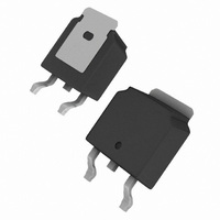
MOSFET P-CH 60V 5.1A DPAK
Manufacturer
Vishay
Type
Power MOSFETr
Specifications of IRFR9014PBF
Transistor Polarity
P-Channel
Fet Type
MOSFET P-Channel, Metal Oxide
Fet Feature
Standard
Rds On (max) @ Id, Vgs
500 mOhm @ 3.1A, 10V
Drain To Source Voltage (vdss)
60V
Current - Continuous Drain (id) @ 25° C
5.1A
Vgs(th) (max) @ Id
4V @ 250µA
Gate Charge (qg) @ Vgs
12nC @ 10V
Input Capacitance (ciss) @ Vds
270pF @ 25V
Power - Max
2.5W
Mounting Type
Surface Mount
Package / Case
DPak, TO-252 (2 leads+tab), SC-63
Minimum Operating Temperature
- 55 C
Configuration
Single
Resistance Drain-source Rds (on)
0.5 Ohm @ 10 V
Drain-source Breakdown Voltage
60 V
Gate-source Breakdown Voltage
+/- 20 V
Continuous Drain Current
5.1 A
Power Dissipation
2500 mW
Maximum Operating Temperature
+ 150 C
Mounting Style
SMD/SMT
Continuous Drain Current Id
-5.1A
Drain Source Voltage Vds
-60V
On Resistance Rds(on)
500mohm
Rds(on) Test Voltage Vgs
-10V
Threshold Voltage Vgs Typ
-4V
Number Of Elements
1
Polarity
P
Channel Mode
Enhancement
Drain-source On-res
0.5Ohm
Drain-source On-volt
60V
Gate-source Voltage (max)
±20V
Operating Temp Range
-55C to 150C
Operating Temperature Classification
Military
Mounting
Surface Mount
Pin Count
2 +Tab
Package Type
DPAK
Lead Free Status / RoHS Status
Lead free / RoHS Compliant
Lead Free Status / RoHS Status
Lead free / RoHS Compliant, Lead free / RoHS Compliant
Available stocks
Company
Part Number
Manufacturer
Quantity
Price
Company:

Part Number:
IRFR9014PBF
Manufacturer:
VISHAY
Quantity:
2 959
Part Number:
IRFR9014PBF
Manufacturer:
IR
Quantity:
20 000


TO-252AA (HIGH VOLTAGE)
Notes
1. Package body sizes exclude mold flash, protrusion or gate burrs. Mold flash, protrusion or gate burrs shall not exceed 0.10 mm per side.
2. Package body sizes determined at the outermost extremes of the plastic body exclusive of mold flash, gate burrs and interlead flash, but
3. The package top may be smaller than the package bottom.
4. Dimension "b" does not include dambar protrusion. Allowable dambar protrusion shall be 0.10 mm total in excess of "b" dimension at maximum
Document Number: 91344
Revision: 15-Sep-08
ECN: S-81965-Rev. A, 15-Sep-08
DWG: 5973
material condition. The dambar cannot be located on the lower radius of the foot.
including any mismatch between the top and bottom of the plastic body.
DIM.
A1
D1
E1
L1
L2
L3
L4
b2
b3
c2
D
H
E
A
L
b
e
c
θ
D1
MIN.
6.40
1.40
0.89
0.64
6.00
9.40
0.64
0.77
5.21
2.20
0.00
0.45
0.45
5.30
4.40
0'
E1
MILLIMETERS
0.508 BSC
2.286 BSC
2.743 REF
c
A
θ
MAX.
10.40
c2
6.73
1.77
1.27
1.01
6.22
0.88
1.14
5.46
2.38
0.13
0.60
0.58
A1
L
L2
10'
-
-
L1
D
b
b3
E
e
b2
0.252
0.055
0.035
0.025
0.236
0.370
0.025
0.030
0.205
0.087
0.000
0.018
0.018
0.209
0.173
MIN.
Package Information
0'
L3
L4
H
0.108 REF
0.020 BSC
0.090 BSC
INCHES
Vishay Siliconix
MAX.
0.265
0.070
0.050
0.040
0.245
0.409
0.035
0.045
0.215
0.094
0.005
0.024
0.023
www.vishay.com
10'
-
-
1
Related parts for IRFR9014PBF
Image
Part Number
Description
Manufacturer
Datasheet
Request
R

Part Number:
Description:
Power MOSFET(Vdss=100V, Rds(on)=0.21ohm, Id=9.4A)
Manufacturer:
IRF [International Rectifier]
Datasheet:
Part Number:
Description:
Advanced Power MOSFET
Manufacturer:
FAIRCHILD [Fairchild Semiconductor]
Datasheet:

Part Number:
Description:
357-036-542-201 CARDEDGE 36POS DL .156 BLK LOPRO
Manufacturer:
Vishay
Datasheet:
Part Number:
Description:
357-036-542-201 CARDEDGE 36POS DL .156 BLK LOPRO
Manufacturer:
Vishay
Datasheet:
Part Number:
Description:
357-036-542-201 CARDEDGE 36POS DL .156 BLK LOPRO
Manufacturer:
Vishay
Datasheet:
Part Number:
Description:
357-036-542-201 CARDEDGE 36POS DL .156 BLK LOPRO
Manufacturer:
Vishay
Datasheet:
Part Number:
Description:
357-036-542-201 CARDEDGE 36POS DL .156 BLK LOPRO
Manufacturer:
Vishay
Datasheet:
Part Number:
Description:
357-036-542-201 CARDEDGE 36POS DL .156 BLK LOPRO
Manufacturer:
Vishay
Datasheet:
Part Number:
Description:
357-036-542-201 CARDEDGE 36POS DL .156 BLK LOPRO
Manufacturer:
Vishay
Datasheet:
Part Number:
Description:
357-036-542-201 CARDEDGE 36POS DL .156 BLK LOPRO
Manufacturer:
Vishay
Datasheet:
Part Number:
Description:
357-036-542-201 CARDEDGE 36POS DL .156 BLK LOPRO
Manufacturer:
Vishay
Datasheet:
Part Number:
Description:
357-036-542-201 CARDEDGE 36POS DL .156 BLK LOPRO
Manufacturer:
Vishay
Datasheet:
Part Number:
Description:
357-036-542-201 CARDEDGE 36POS DL .156 BLK LOPRO
Manufacturer:
Vishay
Datasheet:
Part Number:
Description:
357-036-542-201 CARDEDGE 36POS DL .156 BLK LOPRO
Manufacturer:
Vishay
Datasheet:
Part Number:
Description:
357-036-542-201 CARDEDGE 36POS DL .156 BLK LOPRO
Manufacturer:
Vishay
Datasheet: