ZXM66P02N8TC Diodes Zetex, ZXM66P02N8TC Datasheet - Page 2
ZXM66P02N8TC
Manufacturer Part Number
ZXM66P02N8TC
Description
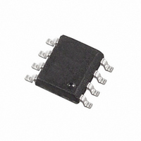
MOSFET P-CHAN 20V 8SOIC
Manufacturer
Diodes Zetex
Datasheet
1.ZXM66P02N8TA.pdf
(5 pages)
Specifications of ZXM66P02N8TC
Fet Type
MOSFET P-Channel, Metal Oxide
Fet Feature
Standard
Rds On (max) @ Id, Vgs
25 mOhm @ 3.2A, 4.5V
Drain To Source Voltage (vdss)
20V
Current - Continuous Drain (id) @ 25° C
6.4A
Vgs(th) (max) @ Id
700mV @ 250µA
Gate Charge (qg) @ Vgs
43.3nC @ 4.5V
Input Capacitance (ciss) @ Vds
2068pF @ 15V
Power - Max
1.56W
Mounting Type
Surface Mount
Package / Case
8-SOIC (3.9mm Width)
Lead Free Status / RoHS Status
Lead free / RoHS Compliant


Thermal Characteristics
Electrical Characteristics
Maximum Ratings
Drain-Source voltage
Gate-Source voltage
Continuous Drain current
Pulsed Drain current
Continuous Source current (Body diode)
Pulsed Source current (Body diode)
Power dissipation
Linear derating factor
Thermal Resistance, Junction to Ambient
Operating and storage temperature range
OFF CHARACTERISTICS
Drain-Source Breakdown Voltage
Zero Gate Voltage Drain Current
Gate-Source Leakage
ON CHARACTERISTICS
Gate Threshold Voltage
Static Drain-Source On-Resistance (Note 5)
Forward Transconductance (Notes 5 & 6)
Diode Forward Voltage (Note 5)
Reverse recovery time (Note 6)
Reverse recovery charge (Note 6)
DYNAMIC CHARACTERISTICS (
Input Capacitance
Output Capacitance
Reverse Transfer Capacitance
Total Gate Charge (Note 7)
Gate-Source Charge (Note 7)
Gate-Drain Charge (Note 7)
Turn-On Delay Time (Note 7)
Turn-On Rise Time (Note 7)
Turn-Off Delay Time (Note 7)
Turn-Off Fall Time (Note 7)
Notes:
Notes:
ZXM66P02N8
Document Number DS31965 Rev. 2 - 2
2. For a device surface mounted on 25mm x 25mm FR4 PCB with high coverage of single sided 1oz copper, in still air conditions.
3. Same as note (3), except the device is measured at t ≤ 10 sec.
4. Repetitive rating 25mm x 25mm FR4 PCB, D = 0.05, pulse width 10μs – pulse width limited by maximum junction temperature.
5. Measured under pulsed conditions. Pulse width ≤ 300μs; duty cycle ≤ 2%
6. For design aid only, not subject to production testing.
7. Switching characteristics are independent of operating junction temperatures.
Characteristic
Characteristic
Characteristic
@T
V
GS
A
Note 6
= 25°C unless otherwise specified
= 4.5V
@T
@T
)
A
= 25°C unless otherwise specified
A
= 25°C unless otherwise specified
(Note 3)
T
(Note 2)
(Note 4)
(Note 3)
(Note 4)
(Note 2)
(Note 3)
(Note 2)
(Note 3)
A
= 70°C (Note 3)
Symbol
R
BV
V
DS (ON)
t
t
I
I
C
V
C
C
GS(th)
Q
Q
D(on)
D(off)
DSS
GSS
Q
Q
g
t
oss
t
t
SD
rss
DSS
rr
iss
fs
gs
gd
r
f
rr
g
www.diodes.com
Min
-0.7
2 of 5
-20
⎯
⎯
⎯
⎯
⎯
⎯
⎯
⎯
⎯
⎯
⎯
⎯
⎯
⎯
⎯
⎯
Symbol
Symbol
T
J
V
R
V
, T
I
I
118.4
P
2068
1038
13.3
23.1
12.2
43.3
21.3
14.0
44.3
98.4
DSS
I
DM
I
SM
Typ
506
θ JA
GS
3.5
D
S
D
⎯
⎯
⎯
⎯
⎯
⎯
STG
0.025
0.045
Max
-100
0.95
⎯
⎯
⎯
⎯
⎯
⎯
⎯
⎯
⎯
⎯
⎯
⎯
⎯
⎯
⎯
-1
Diodes Incorporated
A Product Line of
-55 to 150
Unit
μA
nA
nC
nC
nC
nC
ns
pF
pF
pF
ns
ns
ns
ns
Ω
V
V
S
V
Value
Value
-4.15
1.56
12.5
-8.0
-6.5
-6.4
±12
-20
-28
-28
2.5
20
80
50
I
V
V
I
V
V
V
I
I
V
F = 1MHz
V
I
V
I
D
D
S
F
D
D
DS
GS
GS
GS
DS
DS
GS
DD
= -3.2A, di/dt = 100A/μs
= -250μA, V
= -250μA, V
= -3.2A, V
= -3.2A, R
= -3.2A
= -16V, V
= ±12V, V
= -4.5V, I
= -2.5V, I
= -10V, I
= -15V, V
= -10V, V
= -4.5V, V
Test Condition
ZXM66P02N8
GS
G
D
D
D
GS
GS
GS
GS
DS
DS
= 6.0Ω
= -3.2A
DS
= 0V
= -3.2A
= -2.7A
= 0V
= 0V
= -5V
= 0V
= V
= 0V
= -10V,
© Diodes Incorporated
mW/°C
°C/W
GS
Unit
Unit
October 2009
°C
W
V
V
A
A
A
A
Related parts for ZXM66P02N8TC
Image
Part Number
Description
Manufacturer
Datasheet
Request
R

Part Number:
Description:
DIODE ZENER 13V 500MW SOD-123
Manufacturer:
Diodes Zetex
Datasheet:

Part Number:
Description:
DIODE ZENER 13V 200MW SOD-323
Manufacturer:
Diodes Zetex
Datasheet:

Part Number:
Description:
DIODE ZENER 27V 500MW MINIMELF
Manufacturer:
Diodes Zetex
Datasheet:
Part Number:
Description:
DIODE ZENER 16V 200MW SOD-323
Manufacturer:
Diodes Zetex
Datasheet:
Part Number:
Description:
DIODE ZENER 28V 500MW SOD-123
Manufacturer:
Diodes Zetex
Datasheet:

Part Number:
Description:
DIODE ZENER 6.2V 200MW SC70-3
Manufacturer:
Diodes Zetex
Datasheet:

Part Number:
Description:
DIODE ZENER 3.6V 350MW SOT23-3
Manufacturer:
Diodes Zetex
Datasheet:

Part Number:
Description:
DIODE ZENER 4.3V 350MW SOT23-3
Manufacturer:
Diodes Zetex
Datasheet:
Part Number:
Description:
DIODE ZENER 13V 350MW SOT23-3
Manufacturer:
Diodes Zetex
Datasheet:
Part Number:
Description:
DIODE ZENER 16V 350MW SOT23-3
Manufacturer:
Diodes Zetex
Datasheet:

Part Number:
Description:
DIODE SW ARRAY 80V 200MW SOT363
Manufacturer:
Diodes Zetex
Datasheet:

Part Number:
Description:
DIODE SCHOTTKY 45V16A TO220-3
Manufacturer:
Diodes Zetex
Datasheet:
Part Number:
Description:
DIODE SCHOTTKY 45V 20A TO220-3
Manufacturer:
Diodes Zetex
Datasheet:
Part Number:
Description:
DIODE SW FAST DUAL CC SOT23-3
Manufacturer:
Diodes Zetex
Datasheet:
Part Number:
Description:
DIODE HI SPEED SW CC 70V SOT23-3
Manufacturer:
Diodes Zetex
Datasheet: