4140 Cinch Connectors, 4140 Datasheet - Page 68
4140
Manufacturer Part Number
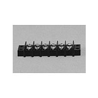
4140
Description
Terminal Block,8 Contacts,0.375 Pitch
Manufacturer
Cinch Connectors
Type
Barrier Stripr
Datasheet
1.4140.pdf
(282 pages)
Specifications of 4140
Number Of Contacts
4POS
Number Of Contact Rows
2
Termination Method
Screw
Mounting Style
Panel
Contact Pitch (mm)
9.53mm
Current Rating (max)
15A
Operating Temp Range
-48C to 148C
Housing Material
Phenolic
Body Orientation
Straight
Operating Voltage (max)
250VAC
Product Height (mm)
28.58mm
Product Length (mm)
54.78mm
Wire Gauge
16
Lead Free Status / RoHS Status
Compliant
Available stocks
Company
Part Number
Manufacturer
Quantity
Price

Part Number:
4140-52
Manufacturer:
PEREGRINE
Quantity:
20 000
Company:
Part Number:
414002-2
Manufacturer:
TE
Quantity:
20 000
Company:
Part Number:
414026-2
Manufacturer:
BOURNS
Quantity:
20


Edge Connector
High Reliability
Insulation Material: Diallyl phthalate, green
Contact Material: Phosphor bronze
Contact Plating: 30µ" selective gold over 50µ" copper in the
Shock: Per MIL-STD-202E, Method 202
Operating Temperature: Dip solder: -65°C to +105°C
Vibration: Per MIL-STD-202E, Method 204, Condition B
Humidity: Per MIL-STD-202E, Method 103, Condition B
Accessories:
Polarizing Key: Two types (order separately):
a) for between-contact polarization and
b) for in-contact polarization
See page 2-74 for more information.
Card Guide Posts: (order separately):
Attach to mounting ears and guide PC board into connector
See page 2-74 for more information.
Individual Contact Insertion and Separation Force:
Call Toll Free: 1 (800) 323-9612
Dip solder tails, single readout, .156" (3.96mm) long or .234" (5.94mm) long.
Dip solder tails, double readout, .156" (3.96mm) or .234" (5.94mm) long on
.200" (5.08mm) row spacing, or .125" (3.18mm) long on .140" (3.56mm) row spacing.
Solder eyelet, single readout and double readout on .200" (5.08mm) row spacing.
Patented bifurcated bellows contacts for added contact reliability.
Ideal for applications involving vibration or board irregularities.
Contact positions: 6, 10, 12, 15, 18, 22, and 25.
Available with or without mounting ears.
Accepts single- or double-sided .062" (1.59mm) thick PC boards.
UL Recognized - file E170218 (UL1977) E130965 (UL1863).
Insulation Resistance:
Withstanding Voltage:
16 oz. maximum with .070" (1.78mm) blade;
1 oz. minimum with .054" (1.37mm) blade
Contact Resistance:
Current Rating:
contact areas, 5µ" gold on tails
Solder eyelet: -65°C to +125°C
1800 VAC RMS (@ sea level)
5 Amps
Dip solder: 6 Milliohms
Solder eyelet: 10 Milliohms
5000 Megohms minimum
.156" (3.96mm) Density Dip
Solder/Solder Eyelet
2-66
Marketed exclusively through distribution.
Related parts for 4140
Image
Part Number
Description
Manufacturer
Datasheet
Request
R

Part Number:
Description:
Standard Card Edge Connectors CINCH BLK CARD GUIDE
Manufacturer:
Cinch Connectors

Part Number:
Description:
TERMINAL BLOCK JUMPER TYPE F
Manufacturer:
Cinch Connectors
Datasheet:
Part Number:
Description:
D-Subminiature Connectors MCHNED PIN 20-24AWG
Manufacturer:
Cinch Connectors
Datasheet:
Part Number:
Description:
Terminal Block,4 Contacts,0.44 Pitch
Manufacturer:
Cinch Connectors
Datasheet: