6140 Cinch Connectors, 6140 Datasheet - Page 87
6140
Manufacturer Part Number
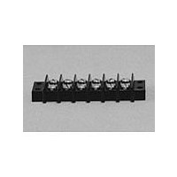
6140
Description
Terminal Block,12 Contacts,0.375 Pitch
Manufacturer
Cinch Connectors
Type
Barrier Stripr
Datasheet
1.6140.pdf
(282 pages)
Specifications of 6140
Number Of Contacts
6POS
Number Of Contact Rows
2
Termination Method
Screw
Mounting Style
Panel
Contact Pitch (mm)
9.53mm
Current Rating (max)
15A
Operating Temp Range
-48C to 148C
Housing Material
Phenolic
Body Orientation
Straight
Operating Voltage (max)
250VAC
Product Height (mm)
28.58mm
Product Length (mm)
73.83mm
Wire Gauge
16
Lead Free Status / RoHS Status
Compliant
Available stocks
Company
Part Number
Manufacturer
Quantity
Price
Company:

Part Number:
6140-1004
Manufacturer:
SUMITOMO
Quantity:
50 000
Company:
Part Number:
61400-1
Manufacturer:
TE
Quantity:
20 000
Company:
Part Number:
61400-1
Manufacturer:
DELPHI
Quantity:
35 000
Company:
Part Number:
61400413321
Manufacturer:
WE
Quantity:
12 000
Company:
Part Number:
61400416021
Manufacturer:
WE
Quantity:
12 000
Part Number:
61407-3
Manufacturer:
TE/泰科
Quantity:
20 000


CN0942 Series: Fluorosilicone Inserts
T
Designator
*
**
NOTES:
1
CN0944 Series: Neoprene Inserts
Termination Term
Designator Type
*
**
NOTES:
1
CN0942/CN0944 Series (C48 Family)
Short Receptacle Connectors
Non-Removable Contacts
ermination Contact Termination
For other modifications, class, etc., consult factory.
For mounting hole dimensions, see page 3-20.
For other modifications, class, etc., consult factory.
For mounting hole dimensions, see page 3-20.
01*
02*
03**
04**
06*
01*
02*
03**
04**
06*
Applies to CN0944B/CN0944C.
Applies to CN0944D/CN0944E.
Applies to CN0942B/CN0942C.
Applies to CN0942D/CN0942E.
T & W
P & S
X & Y
P & S
Style
X & Y
W
B
C
B
C
T Min. S + .002
T Min. S + .002
.250
.230
.144
.124
.900
.250
.230
.144
.124
.900
Termination
.025
.025
.025
.025
.025
.025
N/A
N/A
N/A
N/A
Ordering Information
Series Designation
Series Modification
B - Square-Flange Mount Bayonet Coupled
C - Square-Flange Mount Thread Coupled
D - Single-Hole Mount Bayonet Coupled
E - Single-Hole Mount Thread Coupled
Shell Size
8, 10, 12, 14, 16, 18, 20, 22, & 24
Class
G - Cadmium/Nickel Finish
J - Anodized Finish
N - Electroless Nickel Finish
Insert Arrangement
(See page 3-4)
Series Designation
CN0944
Series Modification
B - Square-Flange Mount Bayonet Coupled
C - Square-Flange Mount Thread Coupled
D - Single-Hole Mount Bayonet Coupled
E - Single-Hole Mount Thread Coupled
Shell Size
8, 10, 12, 14, 16, 18, 20, 22, & 24
Ordering Information
Environmental Class
G - Cadmium/Nickel Finish
N - Electroless Nickel Finish
R - Anodized Finish
3-10
1
CN0942 B 10 J 05 P N O1
1
CN0944 B 10 R 05 P N C O1
Call Toll Free: 1 (800) 323-9612
Contact Style
• Solder Pin Terminal
P - Pin
S - Socket
• Solder Cup Terminal
X - Pin
Y - Socket
• Wire Wrap Terminal
T - Pin
W - Socket
Termination
(See table)
Shell Position
N, 6, 7, 8, 9, Y (See page 3-4)
Termination
(See table)
Termination Type
B - Solder Pin
C - Solder Cup
W - Wire Wrap
Shell Position
N, 6, 7, 8, 9, Y (See page 3-4)
Contact Style
P - Pin
S - Socket
Insert Arrangement
(See page 3-4)
3
Related parts for 6140
Image
Part Number
Description
Manufacturer
Datasheet
Request
R

Part Number:
Description:
Standard Card Edge Connectors CINCH BLK CARD GUIDE
Manufacturer:
Cinch Connectors

Part Number:
Description:
TERMINAL BLOCK JUMPER TYPE F
Manufacturer:
Cinch Connectors
Datasheet:
Part Number:
Description:
D-Subminiature Connectors MCHNED PIN 20-24AWG
Manufacturer:
Cinch Connectors
Datasheet:
Part Number:
Description:
Terminal Block,4 Contacts,0.44 Pitch
Manufacturer:
Cinch Connectors
Datasheet:

Part Number:
Description:
Terminal Block,8 Contacts,0.375 Pitch
Manufacturer:
Cinch Connectors
Datasheet: