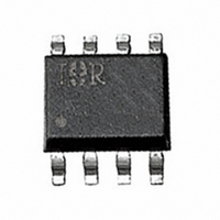
IRF7701 International Rectifier, IRF7701 Datasheet

IRF7701
Specifications of IRF7701
Available stocks
Related parts for IRF7701
IRF7701 Summary of contents
Page 1
... Maximum Junction-to-Ambient JA www.irf.com HEXFET V R DSS DS(on) 0.011@V -12V 0.015@V 0.022 Max. @ -4. -4.5V ±8.0 GS 0.96 ± 8.0 - 150 Max 93940 IRF7701 ® Power MOSFET max -4.5V -10A GS = -2.5V -8. -1.8V -7.0A GS TSSOP-8 Units -12 V ±10 A ±80 1 mW/°C V °C Units 83 °C/W 1 6/21/00 ...
Page 2
... IRF7701 Electrical Characteristics @ T Parameter V Drain-to-Source Breakdown Voltage (BR)DSS Breakdown Voltage Temp. Coefficient (BR)DSS J R Static Drain-to-Source On-Resistance DS(on) V Gate Threshold Voltage GS(th) g Forward Transconductance fs I Drain-to-Source Leakage Current DSS Gate-to-Source Forward Leakage I GSS Gate-to-Source Reverse Leakage Q Total Gate Charge g Q Gate-to-Source Charge ...
Page 3
... BOTTOM 10 1 ° 0.1 10 0.1 -V Fig 2. Typical Output Characteristics 2.0 -10A ° 1.5 1.0 0.5 0.0 2.5 3.0 -60 -40 -20 Fig 4. Normalized On-Resistance IRF7701 VGS -7.00V -4.5V -3.0V -2.5V -1.8V -1.5V -1.2V -1.0V -1.0V 20µs PULSE WIDTH ° 150 Drain-to-Source Voltage ( -4.5V GS ...
Page 4
... IRF7701 8000 0V MHZ C iss = rss = oss = 6000 Ciss 4000 Coss 2000 Crss Drain-to-Source Voltage (V) Fig 5. Typical Capacitance Vs. Drain-to-Source Voltage 100 ° 150 ° 0.1 0.2 0.4 0.6 0.8 -V ,Source-to-Drain Voltage (V) SD Fig 7. Typical Source-Drain Diode Forward Voltage SHORTED 100 Fig 6. Typical Gate Charge Vs. ...
Page 5
... Fig 10. Typical Effective Transient Thermal Impedance, Junction-to-Ambient www.irf.com Pulse Width Duty Factor Fig 10a. Switching Time Test Circuit t d(on 10% 125 150 ° 90 Fig 10b. Switching Time Waveforms Notes: 1. Duty factor Peak 0.01 0 Rectangular Pulse Duration (sec) 1 IRF7701 D.U. µ d(off ...
Page 6
... IRF7701 0.05 0.04 0. -10A 0.02 0.01 0.00 1.5 2.5 -V GS, Gate -to -Source Voltage (V) Fig 11. Typical On-Resistance Vs. Gate Voltage Charge Fig 13a. Basic Gate Charge Waveform 6 0.020 0.015 0.010 0.005 3.5 4.5 0 Fig 12. Typical On-Resistance Vs. Drain 12V V GS Fig 13b. Gate Charge Test Circuit ...
Page 7
... Temperature ( °C ) Fig 14. Threshold Voltage Vs. Temperature www.irf.com -250µ 100 125 150 0.01 Fig 15. Typical Power Vs. Time IRF7701 0.10 1.00 10.00 100.00 Time (sec) 7 ...
Page 8
... IRF7701 TSSOP-8 Part Marking Information EXAMPLE: T HIS IS AN IRF7702 LOT CODE (XX) XXYW PART NUMBER 7702 DAT E CODE EXAMPLES : 9503 = 5C 9532 = EF WORK WEEK 27-52, ALPHANUMERIC YEAR CODE (A,B, ...ETC.) TSSOP-8 Tape and Reel DAT E CODE (YW) T ABLE 1 WORK WEEK 1-26, NUMERIC YEAR CODE (1,2, ....ET C.) ...
Page 9
... IR TAIWAN:16 Fl. Suite D. 207, Sec. 2, Tun Haw South Road, Taipei, 10673 Tel: 886-(0)2 2377 9936 www.irf.com IR CANADA: 15 Lincoln Court, Brampton, Ontario L6T3Z2, Tel: (905) 453 2200 IR GERMANY: Saalburgstrasse 157, 61350 Bad Homburg Tel (0) 6172 96590 IR ITALY: Via Liguria 49, 10071 Borgaro, Torino Tel 011 451 0111 Data and specifications subject to change without notice. 6/00 IRF7701 9 ...


