BC807-40-7-F Diodes Zetex, BC807-40-7-F Datasheet
BC807-40-7-F
Specifications of BC807-40-7-F
Available stocks


Related parts for BC807-40-7-F


BC807-40-7-F Summary of contents
Page 1
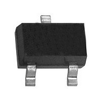
... Lead Free Plating (Matte Tin Finish annealed over Alloy 42 leadframe) • Pin Connections: See Diagram • Ordering Information: See Page 3 • Marking Information: See Page 3 - BC807-16 5A, K5A - BC807-25 5B, K5B - BC807-40 5C, K5C • Weight: 0.008 grams (approximate) Maximum Ratings @T = 25°C unless otherwise specified ...
Page 2
... Fig. 2, Typical Gain-Bandwidth Product vs Collector Current 1,000 100 -50 C ° 10 0.1 100 1,000 Fig. 4, Typical DC Current Gain vs Collector Current 100 COLLECTOR-EMITTER VOLTAGE (V) CE Fig. 6, Typical Emitter-Collector Characteristics www.diodes.com ° 20MHz -V = 5.0V CE 1.0V 10 100 1,000 100 1,000 -I , COLLECTOR CURRENT (mA BC807-16/-25/-40 © Diodes Incorporated ...
Page 3
... Diodes Incorporated products are not authorized for use as critical components in life support devices or systems without the expressed written approval of the President of Diodes Incorporated. DS11208 Rev Packaging SOT-23 XXX = Product Type Marking Code (See Page 1): e.g. K5A = BC807- Date Code Marking XXX Y = Year ex 2006 M = Month ex September ...