9230-44-RC Bourns Inc., 9230-44-RC Datasheet
9230-44-RC
Manufacturer Part Number
9230-44-RC
Description
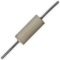
Ind RF Choke Molded 10uH 10% 7.9MHz 55Q-Factor Ferrite 180mA AXL Bag
Manufacturer
Bourns Inc.
Type
RF Choker
Series
9230r
Datasheet
1.9230-32-RC.pdf
(2 pages)
Specifications of 9230-44-RC
Product Length
6.6 mm
Lead Style
Axial
Core Material
Ferrite
Inductance
10 uH
Tolerance
10 %
Self Resonant Frequency
50 MHz
Dimensions
0.095 in Dia. x 0.25 in L
Shielding
Unshielded
Test Frequency
7.9 MHz
Maximum Dc Current
180 mAmps
Maximum Dc Resistance
3.7 Ohms
Q Minimum
55
Operating Temperature Range
- 55 C to + 125 C
Termination Style
Axial
Inductance Tolerance
± 10%
Dc Resistance Max
3.7ohm
Dc Current Rating
180mA
Q Factor
55
Inductor Case Style
Axial Leaded
No. Of Pins
2
Lead Free Status / RoHS Status
Lead free / RoHS Compliant
Lead Free Status / RoHS Status
Lead free / RoHS Compliant
Available stocks
Company
Part Number
Manufacturer
Quantity
Price

Part Number:
9230-44-RC
Manufacturer:
BOURNS/伯恩斯
Quantity:
20 000


*RoHS Directive 2002/95/EC Jan 27 2003 including Annex
Specifications are subject to change without notice.
Customers should verify actual device performance in their specific applications.
Bourns Part No.
9230-94-RC
9230-96-RC
9230-00-RC
9230-02-RC
9230-04-RC
9230-06-RC
9230-08-RC
9230-10-RC
9230-12-RC
9230-14-RC
9230-16-RC
9230-18-RC
9230-20-RC
9230-22-RC
9230-24-RC
9230-26-RC
9230-28-RC
9230-30-RC
9230-32-RC
9230-34-RC
9230-36-RC
9230-38-RC
9230-40-RC
9230-42-RC
9230-44-RC
9230-46-RC
9230-48-RC
9230-50-RC
9230-52-RC
9230-54-RC
9230-56-RC
9230-58-RC
9230-60-RC
9230-62-RC
9230-64-RC
9230-66-RC
9230-68-RC
9230-70-RC
9230-72-RC
9230-74-RC
9230-76-RC
9230-78-RC
9230-80-RC
9230-82-RC
9230-84-RC
9230-86-RC
9230-88-RC
9230-90-RC
9230-92-RC
Electrical Specifications
1000
0.10
0.12
0.15
0.18
0.22
0.27
0.33
0.39
0.47
0.56
0.68
0.82
(µ µ H)
100
120
150
180
220
270
330
390
470
560
680
820
1.0
1.2
1.5
1.8
2.2
2.7
3.3
3.9
4.7
5.6
6.8
8.2
10
12
15
18
22
27
33
39
47
56
68
82
Inductance
Tol. (%)
±10
±10
±10
±10
±10
±10
±10
±10
±10
±10
±10
±10
±10
±10
±10
±10
±10
±10
±10
±10
±10
±10
±10
±10
±10
±10
±10
±10
±10
±10
±10
±10
±10
±10
±10
±10
±10
±10
±10
±10
±10
±10
±10
±10
±10
±10
±10
±10
±10
Min.
40
40
38
35
33
33
30
30
30
30
28
28
25
25
28
30
30
37
45
45
45
50
50
55
55
45
45
50
50
50
45
45
45
45
50
50
50
30
30
30
30
30
30
30
30
30
30
30
30
Q
Frequency
(MHz)
0.79
0.79
0.79
0.79
0.79
0.79
0.79
0.79
0.79
0.79
0.79
0.79
Test
7.9
7.9
7.9
7.9
7.9
7.9
7.9
7.9
7.9
7.9
7.9
7.9
2.5
2.5
2.5
2.5
2.5
2.5
2.5
2.5
2.5
2.5
2.5
2.5
25
25
25
25
25
25
25
25
25
25
25
25
25
9230 Series Molded Axial Inductor
Features
Formerly
High Q value
Inductance range: 0.1 µH to 1000 µH
RoHS compliant*
(MHz)
SRF
690
650
600
550
510
430
410
380
340
300
275
250
230
150
140
125
115
100
Min.
6.5
4.2
3.8
3.4
90
82
75
68
60
55
50
40
35
32
25
22
24
22
20
18
15
14
13
12
11
10
9
8
7
6
5
J. W .Miller
DCR
Max.
0.07
0.08
0.10
0.12
0.14
0.16
0.20
0.30
0.35
0.50
0.60
0.85
1.00
0.18
0.22
0.30
0.40
0.50
0.85
1.0
1.2
1.8
2.0
2.7
3.7
2.7
2.8
3.1
3.3
3.5
3.4
3.6
4.5
5.7
6.7
7.3
8.0
13
15
17
21
25
28
35
42
46
60
65
72
Ω Ω
model
1100
1100
1100
1010
(mA)
935
875
780
640
590
495
450
380
350
825
745
640
550
495
380
350
320
260
245
210
180
210
205
195
190
185
187
180
165
145
135
130
125
Idc
97
85
79
73
65
62
55
50
48
42
40
38
Phenolic
Phenolic
Phenolic
Phenolic
Phenolic
Phenolic
Phenolic
Phenolic
Phenolic
Phenolic
Phenolic
Phenolic
Phenolic
Material
Ferrite
Ferrite
Ferrite
Ferrite
Ferrite
Ferrite
Ferrite
Ferrite
Ferrite
Ferrite
Ferrite
Ferrite
Ferrite
Ferrite
Ferrite
Ferrite
Ferrite
Ferrite
Ferrite
Ferrite
Ferrite
Ferrite
Ferrite
Ferrite
Ferrite
Ferrite
Ferrite
Ferrite
Ferrite
Ferrite
Ferrite
Ferrite
Ferrite
Ferrite
Ferrite
Ferrite
Core
Model
Value Code
Packaging Code
Compliance Code
Examples:
Applications
Temperature Rise .................35 °C at Idc
Operating Temperature
Storage Temperature
Dielectric Strength..................1000 Vrms
Core ...........................Phenolic or Ferrite
Wire .............................Enameled copper
Terminal Coating .................................Sn
Packaging
How To Order
General Specifications
Materials
Electrical Schematic
Ferrite............................-55 °C to +125 °C
Phenolic........................-55 °C to +105 °C
Ferrite............................-55 °C to +125 °C
Phenolic........................-55 °C to +105 °C
Standard..................1000 pcs. per bag
Optional ......5000 pcs. per 14-inch reel
Two-digit code from table
(Example: -02 = 0.18 µ H)
Blank = 1000 pcs./bag
• 9230-00-RC = 0.15 µH packaged 1000 pcs./bag.
• 9230-16-TR-RC = 0.68 µH packaged 5000 pcs./
Filters
Output chokes
14-inch reel.
RC = RoHS compliant*
TR = 5000 pcs./14-inch reel
9230 - 02 - __ - RC
Related parts for 9230-44-RC
Image
Part Number
Description
Manufacturer
Datasheet
Request
R

Part Number:
Description:
RF Inductors 10uH 10%
Manufacturer:
Bourns Inc.
Datasheet:

Part Number:
Description:
Low-Profile Blank Computer Mounting Bracket
Manufacturer:
Keystone Electronics
Datasheet:

Part Number:
Description:
CHOKE RF MOLDED 3.3UH 10% FERRIT
Manufacturer:
JW Miller A Bourns Company
Datasheet:
Part Number:
Description:
CHOKE RF MOLDED 22UH 10% FERRITE
Manufacturer:
JW Miller A Bourns Company
Datasheet:
Part Number:
Description:
CHOKE RF MOLDED 4.7UH 10% FERRIT
Manufacturer:
JW Miller A Bourns Company
Datasheet:
Part Number:
Description:
CHOKE RF MOLDED 2.2UH 10% FERRIT
Manufacturer:
JW Miller A Bourns Company
Datasheet:
Part Number:
Description:
CHOKE RF MOLDED 470UH 10%FERRITE
Manufacturer:
JW Miller A Bourns Company
Datasheet:
Part Number:
Description:
CHOKE RF MOLDED 33UH 10% FERRITE
Manufacturer:
JW Miller A Bourns Company
Datasheet:
Part Number:
Description:
CHOKE RF MOLDED 100UH 10%FERRITE
Manufacturer:
JW Miller A Bourns Company
Datasheet:
Part Number:
Description:
CHOKE RF MOLDED 220UH 10%FERRITE
Manufacturer:
JW Miller A Bourns Company
Datasheet:

Part Number:
Description:
Manufacturer:
Bourns, Inc.
Datasheet:
Part Number:
Description:
11mm Potentiometer
Manufacturer:
Bourns, Inc.
Datasheet:
9230-44-RC Summary of contents
Page 1
... 9230-28-RC 2.2 ±10 30 9230-30-RC 2.7 ±10 37 9230-32-RC 3.3 ±10 45 9230-34-RC 3.9 ±10 45 9230-36-RC 4.7 ±10 45 9230-38-RC 5.6 ±10 50 9230-40-RC 6.8 ±10 50 9230-42-RC 8.2 ±10 55 9230-44-RC 10 ±10 55 9230-46-RC 12 ±10 45 9230-48-RC 15 ±10 45 9230-50-RC 18 ±10 50 9230-52-RC 22 ±10 50 9230-54-RC 27 ±10 50 9230-56-RC 33 ±10 45 9230-58-RC 39 ±10 45 9230-60-RC 47 ± ...
Page 2
... Series Molded Axial Inductor Product Dimensions 0.51 (0.020) Typical Part Marking - MIL-STD Color Code 1st & 2nd Signifi cant Figure Color or Decimal Point Black 0 Brown 1 Red 2 Orange 3 Yellow 4 Green 5 Blue 6 Violet 7 Gray 8 White Gold Decimal Point 29.21 6.35 ± 0.25 (1.15) (.025 ± ...