6-1589455-3 Tyco Electronics, 6-1589455-3 Datasheet - Page 96
6-1589455-3
Manufacturer Part Number
6-1589455-3
Description
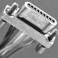
Cable Assembly Strand Wire 0.305m 30AWG 9 POS Rectangular M Crimp
Manufacturer
Tyco Electronics
Series
DUALOBE®r
Specifications of 6-1589455-3
Connector Type
9POS Rectangular
Cable Type
Strand
Gender
M
Cable Length
0.305 m
Termination Method
Crimp
Number Of Positions
9
Number Of Rows
1
Length
1.00' (304.80mm, 12.00")
Color
Multiple, Individual
Shielding
Unshielded
Cable Termination
Crimp
Contact Finish
Nickel
Product Type
Plugs - Housings
Contact Gender
Pin (Male)
Pitch
0.635 mm
Number Of Positions / Contacts
9
Mounting Style
Free Hanging
Mounting Angle
Straight
Latching Type
Unlatched
Termination Style
Wire
Wire Gauge Range
30
Contact Material
Beryllium Copper
Contact Plating
Gold
Voltage Rating
500 V
Current Rating
9 A
Wire Size (awg)
30
Lead Free Status / RoHS Status
Lead free / RoHS Compliant
Features
-
Contact Finish Thickness
-
Usage
-
Pitch - Connector
-
Pitch - Cable
-
Lead Free Status / Rohs Status
Lead free / RoHS Compliant


92
Performance Data
Summary
For Standard Connectors
Catalog 1308638
Revised 8-05
www.tycoelectronics.com
Dimensions are in inches and
millimeters unless otherwise
specified. Values in brackets
are metric equivalents.
Coaxial Connectors
Standard Connectors
Mechanical
Captive Contacts — Terminated con-
nector contacts captivated from move-
ment in both directions.
Cable Retention —
50 Ohm connectors, 15 lb. min.
70 Ohm connectors, 25 lb. min.
93 Ohm connectors, 35 lb. min.
Recommended Coupling Torque
(Threaded Interface) —
8 inch/pounds max.
Recommended Receptacle
Mounting Torque (All Series) —
8 inch/pounds max.
Unmating Force (Slide-On Series) —
1-7 pounds.
Contact Protection (Unmated) —
Pin contact protected by coupling nut
(threaded series)
Connect and Slide-On Series). Socket
protected by insulator and housing.
Assembly Methods
Straight Plugs & Jacks — Cable
Inner Conductor: Soldered to contact.
Cable Shield: Crimped to jerk ring (sol-
der optional).
Angle Plugs — Cable Inner Conductor:
Soldered to contact. Cable Shield:
Soldered to ring & housing.
Environmental
Temperature Range (Continuous
Service) — -85°F to +257°F [-65°C to
+125°C] (with Neoprene gasket or bend
relief cap). -80°F to 392°F [-62°C to
+200°C] (with Silicone gasket or bend
relief cap).
2
or by housing (Quick-
Dimensions are shown for
reference purposes only.
Specifications subject
to change.
1
1
1
Vibration
204, Test condition B (15 G peak). No
physical damage or electrical disconti-
nuities in excess of 1 microsecond.
Shock
213, Test Condition H. No physical dam-
age or electrical discontinuity after
shock.
Thermal Shock — MIL-STD-202,
Method 107, Test Condition B.
Moisture Resistance
202, Method 106.
Salt Spray
101, Test Condition B (48 hours).
Electrical
Impedance — Designed to be com-
patible with 50, 70, or 93 Ohm miniature
coaxial cable.
Dielectric Withstanding Voltage —
1000 volts RMS at sea level.
Contact Resistance — 3 milliohms
max., D.C.
Current Capacity — 3 amps, D.C.
Insulation Resistance — 5 x 10
Megohms min. @ 500 volts D.C.
Voltage Standing Wave Ratio
(VSWR) — Typical 50 Ohm series, 1.2
max. to 2 GHz.
Materials
Housing, Nut, Jerk Ring — Brass
per ASTM-B-16.
Insulator — TEFLON per
ASTM-D-1710.
Pin Contact (Plugs) — Brass per
ASTM-B-16.
3,4
— MIL-STD-202, Method
3,4
USA: 1-800-522-6752
Canada: 1-905-470-4425
Mexico: 01-800-733-8926
C. America: 52-55-5-729-0425
3
— MIL-STD-202, Method
— MIL-STD-202, Method
3
— MIL-STD-
5
3
Socket Contact (Jacks &
Receptacles) — Beryllium Copper
per ASTM-B-196.
Bend Relief Caps (Plugs & Jacks) —
Neoprene or Silicone Rubber per
ZZ-R-765.
Gaskets (Jacks & Receptacles) —
Neoprene or Silicone Rubber per
ZZ-R-765.
Lockwasher — #425 Bronze Alloy.
Plating
Contacts — Gold per MIL-G-45204,
Type II, Grade C, Class 1.
Housing, Nut, Jerk Ring,
Lockwasher — Silver per QQ-S-365,
Type II, Grade A, .0002 [.005] min.
Notes:
1
2
3
4
5
Termination to cables with foamed
dielectrics excluded. Straight con-
nector jerk rings must be soldered
to cable shield.
Pin protector required. See individ-
ual connector specifications.
Screw-On Series, threaded inter-
face.
Tyco Electronics recommends the
use of safety wired connectors in
vibration and shock environment.
See individual specifications for
connectors with safety wire holes.
VSWR is a system specification.
Where performance is critical,
purchase Tyco Electronics cable
assemblies with Screw-On or
Quick-Connect Series connectors
and specify VSWR testing and
mating connector part number.
South America: 55-11-3611-1514
Hong Kong: 852-2735-1628
Japan: 81-44-844-8013
UK: 44-141-810-8967
Related parts for 6-1589455-3
Image
Part Number
Description
Manufacturer
Datasheet
Request
R

Part Number:
Description:
Conn Shrouded Header HDR 15 POS 2.54mm Solder RA Thru-Hole Tube
Manufacturer:
TE Connectivity
Datasheet:

Part Number:
Description:
TERMINAL, SOCKET, FASTON, 18-15AWG
Manufacturer:
TE Connectivity
Datasheet:

Part Number:
Description:
250 FASTON
Manufacturer:
TE Connectivity
Datasheet:
Part Number:
Description:
250 FASTON IS
Manufacturer:
TE Connectivity
Datasheet:

Part Number:
Description:
Power Outlet Strips 6 OUT 15 FT. CORD ON/OFF COMP GRA
Manufacturer:
Wiremold
Datasheet:

Part Number:
Description:
Strip, Power; 6; 15 ft.; UL Listed; Metal; 6 ft.
Manufacturer:
WABER BY TRIPP LITE
Datasheet:
Part Number:
Description:
Strip, Power; 6; 15 ft.; UL Listed; Metal; 6 ft.
Manufacturer:
WABER BY TRIPP LITE
Datasheet:
Part Number:
Description:
Power Strip; 15 ft.; 120VAC; 15A; 6 NEMA 5-15R Outlet; UL Listed; Metal
Manufacturer:
WABER BY TRIPP LITE
Datasheet:
Part Number:
Description:
Strip, Power; 6; 15 ft.; UL Listed; Metal; 6 ft.
Manufacturer:
WABER BY TRIPP LITE
Datasheet:
Part Number:
Description:
Outlet Center, Plug-In; 6; 15 ft.; cULus Listed; Metal; 6 ft.
Manufacturer:
Wiremold
Datasheet:

Part Number:
Description:
Heat Sink Passive BGA Radial Clip Aluminum Die Cast Black Anodized
Manufacturer:
Tyco Electronics
Part Number:
Description:
Conn Wire to Board RCP 64 POS 2.54mm IDT RA Cable Mount T/R
Manufacturer:
Tyco Electronics
Part Number:
Description:
Relay Signal; 5VDC; short pins; tube
Manufacturer:
Tyco Electronics
Part Number:
Description:
Electromechanical Relay DPDT 14A 12VDC 270Ohm Through Hole
Manufacturer:
Tyco Electronics
Datasheet: