646547-1 Tyco Electronics, 646547-1 Datasheet - Page 23
646547-1
Manufacturer Part Number
646547-1
Description
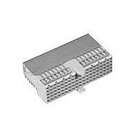
Conn Hard Metric F 110 POS 2mm Press Fit RA Thru-Hole
Manufacturer
Tyco Electronics
Type
Hard Metricr
Datasheet
1.352033-1.pdf
(84 pages)
Specifications of 646547-1
Pitch
2 mm
Number Of Rows
5
Number Of Contacts
110
Termination Method
Press Fit
Mounting
Through Hole
Contact Plating
Gold Over Nickel
Gender
Female
Housing Material
Glass Filled Polyester
Color
Gray
Mounting Angle
Right
Lead Free Status / Rohs Status
Lead free / RoHS Compliant


Product Dimensions
Typical Electrical Properties
Flexible Pin Assignment for
Differential Pair
(AA)S — G = 1:1 Across the Column
Suitable for Data Rate — 2.5 Gb/s and
up
Near End Noise — 3.4%
Far End Noise — 1.4%
(BB) S — G = 1:1 in Column
Suitable for Data Rate — 2.5 Gb/s and
up
Near End Noise — 1.8%
Far End Noise — < 1%
(CC) S — G = 3:1
Suitable for Data Rate — 1.5 Gb/s
Near End Noise — 6.4%
Far End Noise — < 1%
Flexible Pin Assignment for
Single Ended
S — G = 1:1
Frequency — 200MHz (Max 400 Mb/s)
Near End Noise — 4.0%
Far End Noise — 1.2%
Technical Documents
Focus on Global Standards
Consortium
Base Station
OBSAI (Open Base Station Architecture
Initiative) Established in Oct/02: http://
www.obsai.org/index.asp)Nokia/
Samsung/LG/Hyundai/Syscom/ZTE
E-PON (Ethernet Passive Optical
Network)
Not Standards yet but some Ad-hoc
level working group in IEEE802.3
http://www.ieee802.org/3/efm/baseline/
index.html
Catalog 65911
Revised 7-05
www.tycoelectronics.com
—Max. Noise at 100ps Edge Rate
—Max. Noise at 500ps Edge Rate
Dimensions are in millimeters
and inches unless otherwise
specified. Values in brackets
are standard equivalents.
AMP Z-PACK 2mm HM Hard Metric
Interconnection System
4 & 4+1 Row Slim Connectors
Vertical Header
[1.890]
Right Angle Receptacle
48.00
25
[.079]
2.00
[.157]
4.00
Connector Assembly
Exemplary Loaded
13.45
[.530
13.40
[.528
Edge of PC Board
+ 0.00
– 0.10
+ .000
– .004
reference purposes only.
.004
Dimensions are shown for
Specifications subject
to change.
[.079]
0.10
[.079]
2.00
2.00
]
48.00 [1.890]
]
48.00 [1.890]
[1.965]
25
24 x 2.00 =
12 x 4.00 =
49.90
1
z a b c d f
d
c
b
a
Recommended PC Board Thickness 1.60
f
25
Max.
d
b
a
[1.965
f
c
z
[.315]
49.90
8.00
1
Recommended PCB Hole Layout
Recommended PCB Hole Layout
+ 0.00
– 0.10
+ .000
– .004
Component Side Shown
Component Side Shown
(Continued)
]
USA: 1-800-522-6752
Canada: 1-905-470-4425
Mexico: 01-800-733-8926
C. America: 52-55-5-729-0425
48.00 [1.890]
[.146]
[.146]
24 x 2.00 =
A
48.00 [1.890]
48.00 [1.890]
3.70
3.70
11
12 x 4.00 =
24 x 2.00 =
A
Action
Action
Area
Area
Pin
Pin
1
Ref.
Ref.
[.037]
0.95
15
Contact Area
11.85
[.467]
Contact Dimensions
Shield
Max.
[.063]
1.60
[.370]
9.40
11.20
[.441
Ref. Line
Seating Plane Connector
[.346]
8.80
Contact Area
0.16
[.348]
25
8.85
Connector
6.00 [.236]
3 x 2.00 =
[.028]
0.70
+ 0.10
– 0.20
+ .004
– .008
[.063
4 x 2.00 =
8.00 [.315]
]
[.323
8.20
Contact
Area
10.80
[.425]
South America: 55-11-3611-1514
Hong Kong: 852-2735-1628
Japan: 81-44-844-8013
UK: 44-141-810-8967
[.002]
Section A-A
.006
0.05
1
+ 0.10
– 0.20
+ .004
– .008
Contact
d c b a
Area
[.370]
]
9.40
[.059]
1.50
All Holes
]
19.00
[.748]
3 x 2.00 =
6.00 [.236]
[.079]
2.00
10
11
12
13
14
15
16
17
18
19
20
21
22
23
24
25
1
2
3
4
5
6
7
8
9
d
c
b
a
f
Contact Layout
[.002]
[.378]
[.115]
0.05
Action Pin
9.60
2.93
z a b c d f
Area
8.00 [.315]
[.067]
4 x 2.00 =
1.70
[.067]
1.70
All Holes
Ref.
[.130]
3.30
Ref.
23
Related parts for 646547-1
Image
Part Number
Description
Manufacturer
Datasheet
Request
R

Part Number:
Description:
Battery Interconnection System for Portable Electronics; BU CONN FS6 8POS DIP TYPE ASSY ( AMP )
Manufacturer:
Tyco Electronics
Part Number:
Description:
Manufacturer:
Tyco Electronics
Datasheet:
Part Number:
Description:
Manufacturer:
Tyco Electronics
Datasheet:


