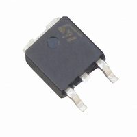
TS820-600B-TR STMicroelectronics, TS820-600B-TR Datasheet - Page 5

TS820-600B-TR
Manufacturer Part Number
TS820-600B-TR
Description
SCR 8A 600V DPAK
Manufacturer
STMicroelectronics
Type
SCRr
Datasheet
1.TYN608RG.pdf
(12 pages)
Specifications of TS820-600B-TR
Scr Type
Sensitive Gate
Voltage - Off State
600V
Voltage - Gate Trigger (vgt) (max)
800mV
Voltage - On State (vtm) (max)
1.6V
Current - On State (it (av)) (max)
5A
Current - On State (it (rms)) (max)
8A
Current - Gate Trigger (igt) (max)
200µA
Current - Hold (ih) (max)
5mA
Current - Off State (max)
5µA
Current - Non Rep. Surge 50, 60hz (itsm)
70A, 73A
Operating Temperature
-40°C ~ 125°C
Mounting Type
Surface Mount
Package / Case
DPak, TO-252 (2 leads+tab), SC-63
Current - On State (it (rms) (max)
8A
Repetitive Peak Off-state Volt
600V
Off-state Voltage
600V
Average On-state Current
5A
Hold Current
5mA
Gate Trigger Current (max)
200uA
Gate Trigger Voltage (max)
800mV
Peak Reverse Gate Voltage
8V
Package Type
DPAK
Peak Repeat Off Current
5uA
Peak Surge On-state Current (max)
73A
On State Voltage(max)
1.6@16AV
Mounting
Surface Mount
Pin Count
2 +Tab
Operating Temp Range
-40C to 125C
Operating Temperature Classification
Automotive
Lead Free Status / RoHS Status
Lead free / RoHS Compliant
Other names
497-5234-2
TS820-600B-TR
TS820-600B-TR
Available stocks
Company
Part Number
Manufacturer
Quantity
Price
TN805, TN815, TS820, TYN608, TYN808, TYN1008
Figure 9.
Figure 11. Surge peak on-state current versus
Figure 13. On-state characteristics (maximum
50.0
10.0
100
10.00
1.0
90
80
70
60
50
40
30
20
10
0.1
1.00
0.10
0.01
0
0.0
1
I
I
TSM
TM
0
dV/dt[R
TN8 / TS8
(A)
(A)
V =0.85V
R =46m
200
T max.:
t0
d
0.5
j
T
j
=max
GK
Relative variation of dV/dt immunity
versus gate-cathode resistance
(typical values) for TS820
number of cycles
values)
400
TYN08
Repetitive
T =110°C
] / dV/dt[
C
1.0
600
10
T =25°C
1.5
R
Non repetitive
T initial=25°C
Number of cycles
j
j
800
GK
R
=220 ]
V
GK
1000
TM
2.0
(k )
(V)
1200
2.5
100
1400
3.0
1600
V = 0.67 x V
t =10ms
p
D
One cycle
T
j
= 125°C
1800
Doc ID 7476 Rev 6
3.5
DRM
2000
1000
4.0
Figure 10. Relative variation of dV/dt immunity
Figure 12. Non-repetitive surge peak on-state
Figure 14. Thermal resistance junction to
100
1000
15.0
12.5
10.0
80
60
40
20
100
7.5
5.0
2.5
0.0
0
10
0.01
R
0
0
dV/dt[C
th(j-a)
I
TSM
20
2
(A), I t (A s)
dI/dt limitation
(°C/W)
GK
Sinusoidal pulse width tp < 10 ms
40
versus gate-cathode capacitance
(typical values) for TS820
current and corresponding values
of I
ambient versus copper surface
under tab (DPAK)
2
4
] / dV/dt[
2
2
60
t
6
0.10
R
80
GK
8
=220 ]
S(cm²)
C
100
t (ms)
p
GK
Epoxy printed circuit board FR4
copper thickness = 35 µm
10
(nF)
120
12
140
TN8 / TS8
1.00
I t
2
Characteristics
14
I
160
TSM
180
16
V = 0.67 x V
TN8 / TS8
TYN08
D
T initial = 25°C
TYN08
R
j
T
GK
j
= 125°C
= 220
200
18
DRM
10.00
5/12
220
20


