ST180S08P0V Vishay, ST180S08P0V Datasheet - Page 7
ST180S08P0V
Manufacturer Part Number
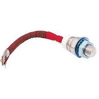
ST180S08P0V
Description
SCR PHASE CONT 800V 200A TO-93
Manufacturer
Vishay
Specifications of ST180S08P0V
Scr Type
Standard Recovery
Voltage - Off State
800V
Voltage - Gate Trigger (vgt) (max)
3V
Voltage - On State (vtm) (max)
1.75V
Current - On State (it (av)) (max)
200A
Current - On State (it (rms)) (max)
314A
Current - Gate Trigger (igt) (max)
150mA
Current - Hold (ih) (max)
600mA
Current - Off State (max)
30mA
Current - Non Rep. Surge 50, 60hz (itsm)
5000A, 5230A
Operating Temperature
-40°C ~ 125°C
Mounting Type
Chassis Mount
Package / Case
TO-209AB, TO-93
Current - On State (it (rms) (max)
314A
Breakover Current Ibo Max
5230 A
Rated Repetitive Off-state Voltage Vdrm
800 V
Off-state Leakage Current @ Vdrm Idrm
30 mA
Forward Voltage Drop
1.75 V
Gate Trigger Voltage (vgt)
3 V
Maximum Gate Peak Inverse Voltage
5 V
Gate Trigger Current (igt)
150 mA
Holding Current (ih Max)
600 mA
Mounting Style
Stud
Peak Repetitive Off-state Voltage, Vdrm
800V
Gate Trigger Current Max, Igt
150mA
Current It Av
200A
On State Rms Current It(rms)
314A
Peak Non Rep Surge Current Itsm 50hz
5kA
Lead Free Status / RoHS Status
Contains lead / RoHS non-compliant
Other names
*ST180S08P0V


www.irf.com
Numb er Of Eq ual Amplitud e Half Cycle Current Pulses (N)
4800
4400
4000
3600
3200
2800
2400
2000
Fig. 5 - Maximum Non-Repetitive Surge Current
1
At Any Rated Load Condition And With
S T 180S S eries
0.001
0.01
Rated V
0.1
0.001
1
S teady S tate Value
R
(DC Operation)
RRM
thJC
Applied Following S urge.
= 0.105 K/ W
10
10000
1000
100
@ 60 Hz 0.0083 s
@ 50 Hz 0.0100 s
Initial T = 125°C
0.01
Fig. 8 - Thermal Impedance Z
0.5 1 1.5 2 2.5 3 3.5 4 4.5 5 5.5 6
Fig. 7 - On-state Voltage Drop Characteristics
Instantaneous On-state Voltage (V)
J
S quare Wave Pulse Duration (s)
T = 25°C
J
100
0.1
S T 180S S eries
S T 180S S eries
thJC
T = 125°C
J
Characteristic
5500
5000
4500
4000
3500
3000
2500
2000
Fig. 6 - Maximum Non-Repetitive Surge Current
0.01
Of Conduc tion May Not Be Maintained.
Maximum Non Repetitive S urge Current
1
S T 180S S eries
Vers us Pulse T rain Duration. Control
Bulletin I25165 rev. C 03/03
Pulse T rain Duration (s)
ST180S Series
No Voltage Reapplied
Rated V
0.1
10
Initial T = 125°C
RRM
Reapplied
J
7
1
Related parts for ST180S08P0V
Image
Part Number
Description
Manufacturer
Datasheet
Request
R


Part Number:
Description:
SIX-CHANNEL DOLBY AC3/MPEG2 AUDIO DECODER
Manufacturer:
STMICROELECTRONICS [STMicroelectronics]
Datasheet:

Part Number:
Description:
357-036-542-201 CARDEDGE 36POS DL .156 BLK LOPRO
Manufacturer:
Vishay
Datasheet:
Part Number:
Description:
357-036-542-201 CARDEDGE 36POS DL .156 BLK LOPRO
Manufacturer:
Vishay
Datasheet:
Part Number:
Description:
357-036-542-201 CARDEDGE 36POS DL .156 BLK LOPRO
Manufacturer:
Vishay
Datasheet:
Part Number:
Description:
357-036-542-201 CARDEDGE 36POS DL .156 BLK LOPRO
Manufacturer:
Vishay
Datasheet:
Part Number:
Description:
357-036-542-201 CARDEDGE 36POS DL .156 BLK LOPRO
Manufacturer:
Vishay
Datasheet:
Part Number:
Description:
357-036-542-201 CARDEDGE 36POS DL .156 BLK LOPRO
Manufacturer:
Vishay
Datasheet:
Part Number:
Description:
357-036-542-201 CARDEDGE 36POS DL .156 BLK LOPRO
Manufacturer:
Vishay
Datasheet:
Part Number:
Description:
357-036-542-201 CARDEDGE 36POS DL .156 BLK LOPRO
Manufacturer:
Vishay
Datasheet:
Part Number:
Description:
357-036-542-201 CARDEDGE 36POS DL .156 BLK LOPRO
Manufacturer:
Vishay
Datasheet:
Part Number:
Description:
357-036-542-201 CARDEDGE 36POS DL .156 BLK LOPRO
Manufacturer:
Vishay
Datasheet:
Part Number:
Description:
357-036-542-201 CARDEDGE 36POS DL .156 BLK LOPRO
Manufacturer:
Vishay
Datasheet:
Part Number:
Description:
357-036-542-201 CARDEDGE 36POS DL .156 BLK LOPRO
Manufacturer:
Vishay
Datasheet: