1-104071-1 Tyco Electronics, 1-104071-1 Datasheet - Page 204
1-104071-1
Manufacturer Part Number
1-104071-1
Description
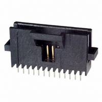
Conn Shrouded Header HDR 12 POS 1.27mm Solder ST Thru-Hole Tube
Manufacturer
Tyco Electronics
Type
Shrouded Headerr
Series
AMPMODU® System 50r
Specifications of 1-104071-1
Pitch
1.27 mm
Number Of Rows
1
Number Of Contacts
12
Gender
HDR
Contact Plating
Gold Over Nickel
Termination Method
Solder
Connector Type
Shrouded
Number Of Positions
12
Number Of Positions Loaded
All
Height Stacking (mating)
0.175", 0.450" (4.45mm, 11.43mm)
Molding Height Above Board
0.390" (9.91mm)
Contact Mating Length
0.125" (3.18mm)
Mounting Type
Through Hole
Termination
Solder
Contact Finish
Gold
Contact Finish Thickness
30µin (0.76µm)
Color
Black
Lead Free Status / RoHS Status
Contains lead / RoHS non-compliant
Features
-
Row Spacing
-
Lead Free Status / RoHS Status
Contains lead / RoHS non-compliant
Other names
1-104071-1
A0102
A0102


5
204
Material
Black polyester
Technical Documents
The barrier insert can be
used on double row headers
(.100 x .100 [2.54 x 2.54]
centers), including shrouded
versions—3 and 4 sides,
as well as unshrouded
straight post headers. With
one barrier insert several
configurations can be
obtained, providing headers
with capabilities of accept-
ing various combinations of
polarized and non-polarized
AMPMODU connectors.
For unshrouded headers,
the barrier insert is used
to establish polarization
and to compartmentalize
the header. For shrouded
headers, the barrier insert is
used to compartmentalize
the header, while maintaining
polarization. The barrier
insert itself is notched to
facilitate cutting off the
ends with a simple tool
such as tin snips or scissors
to achieve the desired
configuration.
Catalog 1307819
Revised 8-08
www.tycoelectronics.com
— page 276
are metric equivalents.
Dimensions are in inches and
millimeters unless otherwise
specified. Values in brackets
AMPMODU Interconnection System
Accessories: Barrier Insert, Part No. 87743-1
Barrier Insert Cutoffs
Typical Barrier Insert Applications
For Unshrouded Double-Row, Straight Post Headers,
.100 x .100 [2.54 x 2.54] Centers
Note: All configurations of barrier inserts compartmentalize headers and maintain polarization,
For Shrouded Double-Row, 3 and 4 Sided Headers,
.100 x .100 [2.54 x 2.54] Centers
Note: Right-angle (Figs. 2 and 3) and “T” (Fig. 1) configurations of barrier insert establish
Note: All part numbers are RoHS compliant.
[7.98]
.314
(Left and Right Sides)
[0.94]
.037
Partial Cutoff
except bar (Fig. 4) configuration, which is used primarily for compartmentalizing headers.
polarization; bar (Fig. 4) configuration of barrier insert compartmentalizes header.
Fig. 1
See Fig. 2
See Fig. 3
[11.33]
Dimensions are shown for
reference purposes only.
Specifications subject
to change.
.446
[3.23]
.127
Complete Cutoff
Partial Cutoff
(Right Side)
(Left Side)
Fig. 2
See Fig. 4
See Fig. 4
USA: 1-800-522-6752
Canada: 1-905-470-4425
Mexico: 01-800-733-8926
C. America: 52-55-1106-0803
[8.64]
.340
45°
See Fig. 1
See Fig. 1
Complete Cutoff
Partial Cutoff
(Right Side)
(Left Side)
[0.76]
.030
Fig. 3
[2.29]
.090
[2.54]
South America: 55-11-2103-6000
Hong Kong: 852-2735-1628
Japan: 81-44-844-8013
UK: 44-8706-080-208
.100
[2.21]
[1.19]
.087
.047
(Left and Right Sides)
See Fig. 2
Complete Cutoff
See Fig. 3
Fig. 4
Thru Typ. (2)
[0.74±0.03]
Dia. x
[0.79-1.09]
remainder
.029±.001
.031-.043
[0.76]
Deep—
.030
Dia.
[2.39]
.094
[6.35]
.250[
Related parts for 1-104071-1
Image
Part Number
Description
Manufacturer
Datasheet
Request
R

Part Number:
Description:
Conn Wire to Board HDR 10 POS 2.54mm Solder ST Thru-Hole
Manufacturer:
TE Connectivity
Datasheet:

Part Number:
Description:
Conn Shrouded Header HDR 10 POS 2mm Solder ST Thru-Hole
Manufacturer:
TE Connectivity
Datasheet:

Part Number:
Description:
Conn Wire to Board HDR 10 POS 2.54mm Solder RA Thru-Hole
Manufacturer:
TE Connectivity
Datasheet:

Part Number:
Description:
Conn IDC Connector PL 10 POS 2.54mm IDT RA Cable Mount Bulk
Manufacturer:
TE Connectivity
Datasheet:

Part Number:
Description:
TIMER, CONNECTOR HOUSING, 10 POS
Manufacturer:
TE Connectivity
Datasheet:

Part Number:
Description:
Switch Tactile OFF (ON) SPST Round Button PC Pins 0.05A 24VDC 1.57N Thru
Manufacturer:
Tyco Electronics
Datasheet:
Part Number:
Description:
Conn Wire to Board RCP 14 POS 2.54mm Solder ST Thru-Hole
Manufacturer:
Tyco Electronics
Datasheet:
Part Number:
Description:
7,5mm MINI HVL CABLE ASSEMBLY length 2000mm White
Manufacturer:
Tyco Electronics
Part Number:
Description:
Tubular 14AWG 18mm 4.7mm Galvanic Tin Bulk
Manufacturer:
Tyco Electronics
Part Number:
Description:
Electromechanical Relay DPDT 15A 48VDC 5.52KOhm Through Hole
Manufacturer:
Tyco Electronics
Datasheet:
Part Number:
Description:
RZ01-1C4-D024
Manufacturer:
Tyco Electronics
Datasheet: