UMA4NT1 ON Semiconductor, UMA4NT1 Datasheet

TRANS BRT PNP DUAL SS SOT-353

UMA4NT1

Manufacturer Part Number
UMA4NT1
Description
TRANS BRT PNP DUAL SS SOT-353
Manufacturer
ON Semiconductor
Datasheet

Specifications of UMA4NT1

Transistor Type
2 PNP - Pre-Biased (Dual)
Current - Collector (ic) (max)
100mA
Voltage - Collector Emitter Breakdown (max)
50V
Resistor - Base (r1) (ohms)
10K
Dc Current Gain (hfe) (min) @ Ic, Vce
160 @ 5mA, 10V
Vce Saturation (max) @ Ib, Ic
250mV @ 300µA, 10mA
Current - Collector Cutoff (max)
500nA
Power - Max
150mW
Mounting Type
Surface Mount
Package / Case
SC-70-5, SC-88A, SOT-323-5, SOT-353, 5-TSSOP
Lead Free Status / RoHS Status
Contains lead / RoHS non-compliant
Frequency - Transition
-
Resistor - Emitter Base (r2) (ohms)
-
Other names
UMA4NT1OS

Available stocks

Company
Part Number
Manufacturer
Quantity
Price
Part Number:
UMA4NT1
Manufacturer:
ON
Quantity:
13 468
UMA4NT1, UMA6NT1
Dual Common Emitter Bias
Resistor Transistors
PNP Silicon Surface Mount Transistors
with Monolithic Bias Resistor Network
a monolithic bias network consisting of two resistors; a series base
resistor and a base−emitter resistor. These digital transistors are
designed to replace a single device and its external resistor bias
network. The BRT eliminates these individual components by
integrating them into a single device. In the UMC2NT1 series, two
BRT devices are housed in the SOT−353 package which is ideal for
low power surface mount applications where board space is at a
premium.
Features
Stresses exceeding Maximum Ratings may damage the device. Maximum
Ratings are stress ratings only. Functional operation above the Recommended
Operating Conditions is not implied. Extended exposure to stresses above the
Recommended Operating Conditions may affect device reliability.
1. Device mounted on a FR-4 glass epoxy printed circuit board using the
MAXIMUM RATINGS
and Q
© Semiconductor Components Industries, LLC, 2006
May, 2006 − Rev. 4
THERMAL CHARACTERISTICS
DEVICE RESISTOR VALUES
Collector-Base Voltage
Collector-Emitter Voltage
Collector Current
Thermal Resistance, Junction-to-Ambient
(Surface Mounted)
Operating and Storage Temperature Range
Total Package Dissipation @ T
(Note 1)
UMA4NT1
UMA6NT1
The BRT (Bias Resistor Transistor) contains a single transistor with
Simplifies Circuit Design
Reduces Board Space
Reduces Component Count
Pb−Free Packages are Available
minimum recommended footprint.
2
, − minus sign for Q
Device
Rating
(T
1
A
(PNP) omitted)
= 25°C unless otherwise noted, common for Q
Preferred Devices
A
= 25°C
R1 (K)
10
47
Symbol
T
V
V
R
J
P
CBO
CEO
, T
I
qJA
C
D
stg
−65 to +150
Value
*150
100
833
50
50
R2 (K)
1
mAdc
°C/W
Unit
Vdc
Vdc
mW
°C
1
†For information on tape and reel specifications,
Preferred devices are recommended choices for future use
and best overall value.
UMA4NT1
UMA4NT1G
UMA6NT1
UMA6NT1G
including part orientation and tape sizes, please
refer to our Tape and Reel Packaging Specification
Brochure, BRD8011/D.
Device
SC−88A/SOT−353
(Note: Microdot may be in either location)
CASE 419A
STYLE 7
ORDERING INFORMATION
R1
Ux = Device Code
M
G
4
http://onsemi.com
Q1
3
= Date Code
= Pb−Free Package
(Pb−Free)
(Pb−Free)
SOT−353
SOT−353
SOT−353
SOT−353
Package
x = 0 or 1
2
Publication Order Number:
3000/Tape & Reel
3000/Tape & Reel
3000/Tape & Reel
3000/Tape & Reel
Q2
1
MARKING
DIAGRAM
R1
Shipping
5
Ux M G
UMA4NT1/D
G

Related parts for UMA4NT1

UMA4NT1 Summary of contents

Page 1

... UMA4NT1, UMA6NT1 Preferred Devices Dual Common Emitter Bias Resistor Transistors PNP Silicon Surface Mount Transistors with Monolithic Bias Resistor Network The BRT (Bias Resistor Transistor) contains a single transistor with a monolithic bias network consisting of two resistors; a series base resistor and a base−emitter resistor. These digital transistors are designed to replace a single device and its external resistor bias network ...

Page 2

... 1.0 kW Output Voltage (off 5 0 1.0 kW Input Resistor 250 200 150 100 50 0 −50 UMA4NT1, UMA6NT1 (T = 25°C unless otherwise noted) A UMA4NT1 UMA6NT1 UMA4NT1 UMA6NT1 UMA4NT1 UMA6NT1 R = 833°C/W qJA 0 50 100 T , AMBIENT TEMPERATURE (°C) A Figure 1. Derating Curve http://onsemi.com ...

Page 3

... TYPICAL ELECTRICAL CHARACTERISTICS − UMA4NT1 75°C A 0.1 0. COLLECTOR CURRENT (mA) C Figure 2. V versus I CE(sat REVERSE BIAS VOLTAGE (VOLTS) R Figure 4. Output Capacitance UMA4NT1, UMA6NT1 1000 25°C 100 −25° 100 MHz 25° 75° −25° 0.1 0. Figure 5. Output Current versus Input Voltage http://onsemi ...

Page 4

... TYPICAL ELECTRICAL CHARACTERISTICS − UMA6NT1 25°C 1 0.1 0. COLLECTOR CURRENT (mA) C Figure 6. V versus I CE(sat REVERSE BIAS VOLTAGE (VOLTS) R Figure 8. Output Capacitance UMA4NT1, UMA6NT1 1000 −25° 75°C 100 100 MHz 25° 0.1 0.01 0.001 Figure 9. Output Current versus Input Voltage http://onsemi.com 75°C A − ...

Page 5

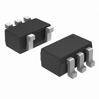
... P.O. Box 5163, Denver, Colorado 80217 USA Phone: 303−675−2175 or 800−344−3860 Toll Free USA/Canada Fax: 303−675−2176 or 800−344−3867 Toll Free USA/Canada Email: orderlit@onsemi.com UMA4NT1, UMA6NT1 PACKAGE DIMENSIONS SC−88A / SOT−353 / SC−70 CASE 419A−02 ISSUE J NOTES: 1 ...

Related keywords