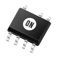
NCP1236BD65R2G ON Semiconductor, NCP1236BD65R2G Datasheet - Page 6

NCP1236BD65R2G
Manufacturer Part Number
NCP1236BD65R2G
Description
IC CTLR CURR MODE 65KHZ 7-SOIC
Manufacturer
ON Semiconductor
Datasheet
1.NCP1236AD65R2G.pdf
(34 pages)
Specifications of NCP1236BD65R2G
Frequency - Max
70kHz
Pwm Type
Current Mode
Number Of Outputs
1
Duty Cycle
85%
Voltage - Supply
9.5 V ~ 28 V
Buck
No
Boost
No
Flyback
Yes
Inverting
No
Doubler
No
Divider
No
Cuk
No
Isolated
Yes
Operating Temperature
-40°C ~ 125°C
Package / Case
8-SOIC (0.154", 3.90mm Width) 7 leads
Duty Cycle (max)
85 %
Output Current
500 mA
Mounting Style
SMD/SMT
Switching Frequency
65 KHz
Operating Supply Voltage
- 0.3 V to + 28 V
Supply Current
+/- 30 mA
Maximum Operating Temperature
+ 125 C
Fall Time
40 ns
Minimum Operating Temperature
- 40 C
Rise Time
40 ns
Lead Free Status / RoHS Status
Lead free / RoHS Compliant
Available stocks
Company
Part Number
Manufacturer
Quantity
Price
Company:
Part Number:
NCP1236BD65R2G
Manufacturer:
ON
Quantity:
5
Company:
Part Number:
NCP1236BD65R2G
Manufacturer:
ON Semiconductor
Quantity:
1 300
Part Number:
NCP1236BD65R2G
Manufacturer:
ON/安森美
Quantity:
20 000
ELECTRICAL CHARACTERISTICS
V
CURRENT SENSE
OVERPOWER COMPENSATION
FEEDBACK
OVERCURRENT PROTECTION
FREQUENCY FOLDBACK
Input Bias Current
Maximum internal current
setpoint
Propagation delay from V
detection to DRV off
Leading Edge Blanking Duration
for V
Threshold for immediate fault
protection activation
Leading Edge Blanking Duration
for V
Slope of the compensation ramp
Soft−start duration
V
Current flowing out of CS pin
FB voltage above which I
applied
FB voltage below which is no
I
Watchdog timer for dc operation
Internal pull−up resistor
V
division ratio
Internal pull−up voltage on the
FB pin
Fault timer duration
Fault timer duration (for the C
version only)
Autorecovery mode latch−off
time duration
Autorecovery mode latch−off
time duration (for the C version
only)
Feedback voltage threshold
below which frequency foldback
starts
Feedback voltage threshold
below which frequency foldback
is complete
Minimum switching frequency
CC
OPC
HV
FB
= 11 V unless otherwise noted)
to internal current setpoint
ILIM
CS(stop)
to I
applied
OPC
Characteristics
conversion ratio
OPC
Ilimit
is
V
V
V
From 1
V
V
V
V
V
V
T
From CS reaching V
From CS reaching V
V
J
CS
FB
CS
HV
HV
HV
HV
HV
HV
FB
= 25°C
(For typical values T
> 3.5 V
= V
= 0.7 V
= V
= 125 V
= 162 V
= 325 V
= 365 V
= 365 V
= 365 V
st
skip(in)
ILIM
pulse to V
Test Condition
+ 0.2
CS
http://onsemi.com
ILIMIT
ILIMIT
= V
J
= 25°C, for min/max values T
ILIM
to DRV stop
to DRV stop
6
S
S
comp(100kHz)
V
V
comp(65kHz)
V
V
V
I
I
I
I
t
f
Symbol
t
OPC(125)
OPC(162)
OPC(325)
OPC(365)
WD(OPC)
FB(OPCE)
R
OSC(min)
FB(OPCF)
V
t
t
SSTART
FB(foldS)
FB(foldE)
CS(stop)
K
autorec
autorec
V
t
t
I
t
FB(up)
FB(ref)
t
t
delay
K
BCS
bias
LEB
fault
fault
OPC
ILIM
FB
J
= −40°C to +125°C, V
0.66
0.95
2.12
0.85
1.22
Min
190
105
2.8
4.7
4.3
1.0
1.8
90
15
98
16
22
−
−
−
−
−
−
−
−
−
−
−32.5
0.02
1.05
0.54
2.35
2.15
1.00
1.35
Typ
250
120
−50
130
128
110
0.7
4.0
1.5
2.0
80
20
32
20
32
27
0
5
5
HV
= 125 V,
Max
0.74
1.15
2.58
1.35
1.48
110
310
150
150
168
5.2
5.3
5.7
2.0
2.2
25
48
32
−
−
−
−
−
−
−
−
−
mA / V
mV /
Unit
kHz
mA
ms
mA
ms
kW
ms
ms
ns
ns
ns
ms
V
V
V
V
V
V
V
−
s
s


