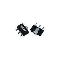
EC1019B-G TriQuint, EC1019B-G Datasheet - Page 3

EC1019B-G
Manufacturer Part Number
EC1019B-G
Description
RF Amplifier DC-4 GHz 18.5dB Gain@2 GHz
Manufacturer
TriQuint
Type
Buffer Amplifierr
Datasheet
1.EC1019B-PCB.pdf
(4 pages)
Specifications of EC1019B-G
Operating Frequency
0 Hz to 4000 MHz
P1db
19.5 dBm at 2 GHz
Noise Figure
2.8 dB
Operating Supply Voltage
4.7 V
Supply Current
70 mA
Maximum Operating Temperature
+ 160 C
Mounting Style
SMD/SMT
Package / Case
SOT-89
Number Of Channels
1 Channel
Lead Free Status / RoHS Status
Lead free / RoHS Compliant
Other names
1066893
Available stocks
Company
Part Number
Manufacturer
Quantity
Price
Company:
Part Number:
EC1019B-G
Manufacturer:
TriQuint Semiconductor
Quantity:
135
Part Number:
EC1019B-G
Manufacturer:
WJ
Quantity:
20 000
WJ Communications, Inc • Phone 1-800-WJ1-4401 • FAX: 408-577-6621 • e-mail: sales@wj.com • Web site: www.wj.com, www.TriQuint.com
1. The proper values for the components are dependent upon the intended frequency of operation.
2. The following values are contained on the evaluation board to achieve optimal broadband performance:
C1, C2, C4
Designator
Reference
L1
S-Parameters (V
Freq (MHz)
1000
1500
2000
2500
3000
3500
4000
4500
5000
5500
6000
500
EC1019B
InGaP HBT Gain Block
50
RF IN
Ref. Desig.
L1
C1, C2
C3
C4
R4
.018 µF
Capacitor
820 nH
Blocking
50
C1
device
-23.95
-21.49
-18.50
-16.41
-16.74
-18.80
-18.23
-11.23
-10.23
-15.66
-15.34
-10.30
S11 (dB)
-8.84
= +4.7 V, I
EC1019B
Recommended Component Values
1000 pF
220 nH
Device S-parameters are available for download off of the website at:
Value / Type
39 nH wirewound inductor
56 pF chip capacitor
0.018 μF chip capacitor
Do Not Place
15 Ω 1% tolerance
500
Resistor
RF Choke
Capacitor
0.018 µF
Bypass
CC
Bias
Icc = 70 mA
R4
-136.32
-169.66
-170.30
170.71
156.68
101.48
S11 (ang)
= 70 mA, T = 25 °C, calibrated to device leads)
-10.27
-53.11
-96.14
C3
C4
57.53
96.95
75.00
47.92
Recommended Application Circuit
L1
Vcc
Capacitor
Blocking
100 pF
68 nH
C2
900
Typical Device S-Parameters
Frequency (MHz)
RF OUT
S21 (dB)
21.26
20.93
20.23
19.32
18.38
17.40
16.26
15.62
14.56
14.06
12.53
12.25
11.61
27 nH
68 pF
1900
Size
0603
0603
0603
0805
22 nH
68 pF
2200
177.77
159.51
141.23
124.62
110.93
S21 (ang)
95.50
86.90
73.24
67.04
52.87
44.96
30.08
22.08
18 nH
56 pF
2500
-23.34
-23.02
-22.37
-21.62
-20.72
-19.86
-19.10
-18.20
-17.79
-17.02
-16.79
-16.32
-15.68
S12 (dB)
15 nH
39 pF
3500
Specifications and information are subject to change without notice
S12 (ang)
14.81
19.01
22.20
22.10
22.75
21.01
19.02
14.17
10.83
1.00
8.39
6.34
4.21
http://www.wj.com
The proper value for R1 is dependent upon the supply
voltage and allows for bias stability over temperature.
WJ recommends a minimum supply bias of +6 V. A
1% tolerance resistor is recommended.
Voltage
Supply
Recommended Bias Resistor Values
10 V
12 V
6 V
7 V
8 V
9 V
-19.31
-17.25
-14.71
-12.45
-10.32
-10.16
-10.15
S22 (dB)
-8.08
-6.62
-7.84
-8.00
-6.73
-5.91
16.4 ohms
30.7 ohms
102 ohms
R1 value
45 ohms
59 ohms
74 ohms
-100.42
-132.99
-161.53
167.27
154.27
139.29
107.37
S22 (ang)
-58.78
82.18
69.95
57.27
36.46
-6.11
Page 3 of 4 January 2008
0805
1210
1210
2010
2010
2512
Size


