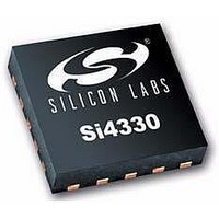
Si4330-V2-FM Silicon Laboratories Inc, Si4330-V2-FM Datasheet - Page 45

Si4330-V2-FM
Manufacturer Part Number
Si4330-V2-FM
Description
RF Receiver RECEIVER EZRadioPRO UNIVERSAL ISM BAND
Manufacturer
Silicon Laboratories Inc
Type
ISM Receiverr
Datasheet
1.SI4330-B1-FM.pdf
(64 pages)
Specifications of Si4330-V2-FM
Package / Case
QFN-20
Operating Frequency
240 MHz to 960 MHz
Operating Supply Voltage
1.8 V to 3.6 V
Maximum Operating Temperature
+ 85 C
Minimum Operating Temperature
- 40 C
Mounting Style
SMD/SMT
Supply Current
100 nA
Lead Free Status / RoHS Status
Lead free / RoHS Compliant
8.5. Low Battery Detector
A low battery detector (LBD) with digital read-out is integrated into the chip. A digital threshold may be programmed
into the lbdt[4:0] field in "Register 1Ah. Low Battery Detector Threshold." When the digitized battery voltage
reaches this threshold an interrupt will be generated on the nIRQ pin to the microcontroller. The microcontroller can
confirm source of the interrupt by reading "Register 03h. Interrupt/Status 1" and “Register 04h. Interrupt/Status 2,”
on page 66.
If the LBD is enabled while the chip is in SLEEP mode, it will automatically enable the RC oscillator which will
periodically turn on the LBD circuit to measure the battery voltage. The battery voltage may also be read out
through "Register 1Bh. Battery Voltage Level" at any time when the LBD is enabled. The low battery detect function
is enabled by setting enlbd=1 in "Register 07h. Operating Mode and Function Control 1".
The LBD output is digitized by a 5-bit ADC. When the LBD function is enabled, enlbd = 1 in "Register 07h.
Operating Mode and Function Control 1", the battery voltage may be read at anytime by reading "Register 1Bh.
Battery Voltage Level." A battery voltage threshold may be programmed in “Register 1Ah. Low Battery Detector
Threshold." When the battery voltage level drops below the battery voltage threshold an interrupt will be generated
on the nIRQ pin to the microcontroller if the LBD interrupt is enabled in “Register 06h. Interrupt Enable 2,” on page
69. The microcontroller will then need to verify the interrupt by reading the interrupt status register, addresses 03
and 04h. The LSB step size for the LBD ADC is 50 mV, with the ADC range demonstrated in the table below. If the
LBD is enabled the LBD and ADC will automatically be enabled every 1 s for approximately 250 µs to measure the
voltage which minimizes the current consumption in Sensor mode. Before an interrupt is activated four consecutive
readings are required.
Ad R/W
1A
1B
R/W
R
Low Battery Detector Threshold
Function/Description
Battery Voltage Level
BatteryVol
ADC Value
…
29
30
31
0
1
2
D7
0
tage
D6
0
1
Rev 1.0
7 .
VDD Voltage [V]
50
D5
0
mV
1.7–1.75
1.75–1.8
3.1–3.15
3.15–3.2
< 1.7
> 3.2
…
vbat[4] vbat[3] vbat[2] vbat[1] vbat[0]
lbdt[4]
D4
ADCValue
lbdt[3]
D3
lbdt[2]
D2
lbdt[1]
Si4330-B1
D1
lbdt[0]
D0
POR Def.
14h
—
45


