2008995-1 TE Connectivity, 2008995-1 Datasheet
2008995-1
Specifications of 2008995-1


Related parts for 2008995-1


2008995-1 Summary of contents
Page 1
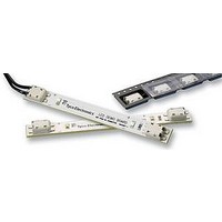
... All numerical values are in metric units [with U.S. customary units in brackets]. Dimensions are in millimeters. Unless NOTE otherwise specified, dimensions have a tolerance of +0.13 and angles have a tolerance of +2_. Figures and i illustrations are for identification only and are not drawn to scale. 1. INTRODUCTION This specification covers the requirements for application of SMT and Through--Hole Poke--In Connectors for use on printed circuit (pc) board based LED strip lighting typically used for sign lighting. The connector accommodates 18, 20 AWG solid copper wires ...
Page 2
Specifications Product Specification 108--2284 provides product performance and test information for the Poke--In Connector; and Design Objective 108--2284--2 provides expected product performance and test information for the Sealed Poke--In Connector. Workmanship Specification 101--21 and Test Specification 109--11 provides solderability ...
Page 3
Strip Length Conductor Stranded Wire (Non - - Acceptable) 3.6. Wire Termination The receptacles must be terminated according to the instructions packaged with the tooling. A. Workmanship The housing must not be damaged in any way. There shall be no ...
Page 4
Strain Relief It is recommended that a means be provided to support the wire bundle extending away from the connector to prevent inadvertent application of high force to the wire bundle from transmitting into the wire/connector interface. When the ...
Page 5
Through- - Hole PC Board Layout 3. Board Hole Dimensions The finished hole size for through--hole applications must meet the dimensional requirements provided in Figure 7. 1.57 +0.18 Board Thickness Tin Thickness (As Required) ...
Page 6
Spacing The connector is able to be placed side--by--side on the pc board when pads are placed on 4.0 mm centers. See Figure 8. Connectors should be handled only by the housing to avoid deformation, contamination, or damage to ...
Page 7
... Contacts must be fluxed prior to soldering with a mildly active, rosin base flux. Selection of the flux will depend on the type of pc board and other components mounted on the board. Additionally, the flux must be compatible with the wave solder line, manufacturing, health, and safety requirements. Flux that is compatible with the connectors is provided in Figure 11 ...
Page 8
... All traces must be covered by solder mask in the solder deposit area. Exposed traces could cause bridging and create CAUTION a short, or wick solder away from the solder tines, producing a weak solder joint hold- - down aperture is required other than that specified, the design must ensure that the connector housing will CAUTION not sit on the solder deposit ...
Page 9
... C. Connectors with Through- Hole Contacts 1. Solderability All solder joints should conform to those specified in Workmanship Specification 101--21 and all other requirements for through--hole contacts specified in this document 2. Process Connectors with through--hole contacts can be soldered using wave soldering or equivalent soldering techniques ...
Page 10
... Figure 16. Consideration must be given to toxicity and other safety requirements recommended by the solvent manufacturer. DANGER Trichloroethylene and Methylene Chloride can be used with no harmful affect to the connectors; however, Tyco Electronics does not recommend them because of the harmful occupational and environmental effects. Both are carcinogenic (cancer- - causing) and Trichloroethylene is harmful to the earth’ ...
Page 11
SMT Poke Connector Soldered on PC Board Solder Joints Evenly Formed Around Contact Tines 3.13. Replacement and Repair The contacts and housings are not repairable. DO NOT use damaged or defective contacts or housings. DO NOT remove the ...
Page 12
VISUAL AID Figure 18 shows a typical application of Poke--in Connectors. This illustration should be used by production personnel to ensure a correctly applied product. Applications which DO NOT appear correct should be inspected using the information in the ...