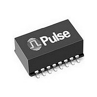
PE-65798 PULSE ELECTRONICS CORPORATION, PE-65798 Datasheet - Page 6

PE-65798
Manufacturer Part Number
PE-65798
Description
Manufacturer
PULSE ELECTRONICS CORPORATION
Datasheet
1.PE-65798.pdf
(8 pages)
Specifications of PE-65798
Operating Temp Range
0C to 70C
Mounting
Surface Mount
Pin Count
16
Interwinding Capacitance Max
100pF
Isolation Voltage (max)
2000VrmsV
Lead Style
Gull Wing
Ocl Inductance (max)
22(Min)mH
Operating Temperature Max Deg. C
70C
Operating Temperature Min Deg. C
0C
Product Depth (mm)
18.29mm
Product Height (mm)
9.91mm
Product Length (mm)
24.13mm
Turns Ratio
1:2.5/1:2.5
Lead Free Status / RoHS Status
Compliant
Available stocks
Company
Part Number
Manufacturer
Quantity
Price
Part Number:
PE-65798T
Manufacturer:
PULSE
Quantity:
20 000
ISDN S-INTERFACE
TRANSFORMERS
Application Notes
(continued from previous page)
www.pulseeng.com
4. Impedance Requirements – The requirements for
5. Common Mode Chokes – The “high frequency” 4-wire
A recommended test setup is shown in Figure 2. A high
inductance “low frequency” common mode choke, such as
PE-65950 or PE-65853, is recommended to improve
balance, or to correct inherent unbalances of some circuits.
minimum impedance in the inactive and powered-down
states are expressed by impedance templates for both
transmitter and receiver in NT and TE. At the low
frequency end of 1MHz, it is reasonable to assume that
the impedance seen from the line is entirely capacitive.
The maximum capacitance budget, derived from the
templates, is somewhat different for the NT and the TE.
Contributors to the total capacitance are: the chip output,
the protection circuit, the transformer, common mode
choke and any other element that may be present. In the
TE case, there is also the maximum allowable TE cord
impedance. Here the maximum budget is 800pF. As a
rule, the capacitances should be kept as low as possible
in the interface circuit design. With the specified trans-
former capacitances, it is possible to remain within budget
and have a reasonable margin for measurement errors.
common mode chokes shown on pages 7 and 8 provide
an effective means of compliance with national and
international regulations on EMI. They are designed to be
used in conjunction with either Pulse’s ISDN S-Interface or
T1/CEPT transformers as shown in Figure 1. A high
inductance “low frequency” common mode choke is
recommended to improve balance, or to correct inherent
unbalances of some ISDN S-Interface circuits.
USA 858 674 8100
• •
UK 44 1483 401 700
Out
Network Analyzer
• •
HP-8751A
France 33 3 84 35 04 04
R
Figure 2. Longitudinal Balance Test Circuit
A
B
• •
Singapore 65 6287 8998
VT
EL
ISM-1 = Wandel and Goltermann
ISM-1
6
Signal Balance Ratio Bridge
6. Surge Voltage Capability for Transformers and Chokes
7. Behavior Under Fault Conditions – Telephony voltages
8. Flammability – Materials used in the products are recog-
• •
Shanghai
may accidentally appear on the ISDN S-Interface line to
the transformer. The transformer will withstand a DC
current of 0.5 Amps for 15 minutes without permanent
damage. Such current may be caused by the telephone
central battery. The transformer will also survive ringing
voltages. These are nominally 120V or 200V maximum at
20 to 60Hz, limited by 1500Ω resistive or 400 to 600Ω
inductive limiting. These may cause peak currents.
nized UL94-VO. Products meet the requirements of IEC
695-2-2 (Needle Flame Test).
• Longitudinal Voltage Peak: 2,400V 10/700µsec
• Metallic Voltage Peak: 800V 10/560µsec
Pri
86 21 32181071
Sec
• •
China 86 769 5538070
Terminating
Resistor
• •
Taiwan 886 2 26980228
T604.D (1/06)


