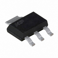
BSP61,115 NXP Semiconductors, BSP61,115 Datasheet - Page 3

BSP61,115
Manufacturer Part Number
BSP61,115
Description
TRANS PNP 80V 500MA SOT223
Manufacturer
NXP Semiconductors
Datasheet
1.BSP62115.pdf
(7 pages)
Specifications of BSP61,115
Package / Case
SOT-223 (3 leads + Tab), SC-73, TO-261
Mounting Type
Surface Mount
Power - Max
1.25W
Current - Collector (ic) (max)
1A
Voltage - Collector Emitter Breakdown (max)
60V
Transistor Type
PNP - Darlington
Current - Collector Cutoff (max)
50nA
Frequency - Transition
200MHz
Dc Current Gain (hfe) (min) @ Ic, Vce
2000 @ 500mA, 10V
Vce Saturation (max) @ Ib, Ic
1.3V @ 500µA, 500mA
Configuration
Single
Transistor Polarity
PNP
Mounting Style
SMD/SMT
Collector- Emitter Voltage Vceo Max
60 V
Emitter- Base Voltage Vebo
5 V
Collector- Base Voltage Vcbo
80 V
Maximum Dc Collector Current
1 A
Power Dissipation
1.25 W
Maximum Operating Temperature
+ 150 C
Continuous Collector Current
- 1 A
Dc Collector/base Gain Hfe Min
1000
Minimum Operating Temperature
- 65 C
Lead Free Status / RoHS Status
Lead free / RoHS Compliant
Other names
933986360115::BSP61 T/R::BSP61 T/R
NXP Semiconductors
THERMAL CHARACTERISTICS
Note
1. Device mounted on a printed-circuit board, single sided copper, tinplated, mounting pad for collector 1 cm
CHARACTERISTICS
T
Note
1. Pulse test: t
2001 May 31
R
R
I
I
h
V
V
f
Switching times (between 10% and 90% levels); see Fig.3
t
t
j
CES
EBO
T
on
off
SYMBOL
SYMBOL
FE
= 25 °C unless otherwise specified.
CEsat
BEsat
PNP Darlington transistors
th j-a
th j-s
For other mounting conditions, see “Thermal considerations for the SOT223 in the General Part of associated
Handbook”.
thermal resistance from junction to ambient
thermal resistance from junction to solder point
collector cut-off current
emitter cut-off current
DC current gain
collector-emitter saturation
voltage
base-emitter saturation voltage
transition frequency
turn-on time
turn-off time
p
BSP60
BSP61
BSP62
≤ 300 μs; δ ≤ 0.02.
PARAMETER
PARAMETER
V
V
V
I
V
I
I
T
I
I
f = 100 MHz
I
I
C
C
C
C
C
Con
Boff
BE
BE
BE
CE
j
I
I
= 150 °C
= 0; V
= −500 mA; I
= −500 mA; I
= −500 mA; I
= −500 mA; V
C
C
= 0.5 mA
= 0; V
= 0; V
= 0; V
= −500 mA; I
= −10 V; note 1; see Fig.2
= −150 mA
= −500 mA
EB
CE
CE
CE
3
CONDITIONS
= −4 V
= −45 V
= −60 V
= −80 V
B
B
B
CE
= −0.5 mA
= −0.5 mA;
= −0.5 mA
Bon
= −5 V;
note 1
CONDITIONS
= −0.5 mA;
BSP60; BSP61; BSP62
−
−
−
−
1 000
2 000
−
−
−
−
−
−
MIN.
VALUE
98
17
−
−
−
−
−
−
−
−
−
200
400
1 500
TYP.
Product data sheet
−50
−50
−50
−50
−
−
−1.3
−1.3
−1.9
−
−
−
MAX.
UNIT
K/W
K/W
2
.
nA
nA
nA
nA
V
V
V
MHz
ns
ns
UNIT


