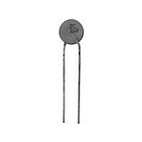
PTCCL11H211HTE Vishay, PTCCL11H211HTE Datasheet - Page 4

PTCCL11H211HTE
Manufacturer Part Number
PTCCL11H211HTE
Description
PTC CP LDD 10D5 A210 265 140 T E3
Manufacturer
Vishay
Series
662r
Type
PTCr
Specifications of PTCCL11H211HTE
Voltage - Max
265V
Current - Hold (ih) (max)
210mA
Current - Trip (it)
315mA
Current - Max
1.3A
Package / Case
Radial
Mounting Style
Through Hole
Pin Count
2
Screening Level
Commercial
Resistance @ 25c
17Ohm
Percentage Of Resistance Tolerance @ 25c
±20
Operating Temperature Min Deg. C
0C
Operating Temperature Max Deg. C
70C
Product Length (mm)
Not Requiredmm
Product Height (mm)
Not Requiredmm
Product Depth (mm)
5.5mm
Lead Free Status / RoHS Status
Contains lead / RoHS non-compliant
R Min/max
-
Time To Trip
-
Lead Free Status / RoHS Status
Contains lead / RoHS non-compliant
Other names
2322 662 52113
232266252113
BC1372
PTCCL11H211HBC
232266252113
BC1372
PTCCL11H211HBC
www.vishay.com
28
2381 66. 5...3/PTCCL..H...HBE
Vishay BCcomponents
PTC THERMISTORS IN BULK
PTC THERMISTORS ON TAPE ON REEL
L
COMPONENTS OUTLINE
TAPE AND REEL ACCORDING TO IEC 60286-2 dimensions in millimeters
SYMBOL
H0
H2
H3
H4
D
P
d
F
T
660
661
662
663
664
D
d
H3
L1
CODE NUMBER 2381
P0
P
P1
D
Seating plane difference (left-right lead)
Fig. 1a
Fig. 1b
P
Component bottom to seating plane
F
Leadcenter to leadcenter distance
Component top to seating plane
(between component and tape)
d
P
T
1
F
D0
H2
62113 - 62513
62813 - 63213
Lead wire clinch height
Pitch of components
Diameter < 12 mm
Diameter ≥ 12 mm
Total thinkness
Body diameter
Lead diameter
PARAMETER
5...3
6...3
5...3
6...3
5...3
5...3
5...3
W2
W0
t
T
For technical questions, contact:
W1 W
H0 H1
For Overload Protection
265 V PTC Thermistors
h
T
H2
h
H3
DIMENSIONS OF BULK TYPE PTC’S (in mm)
1500
1500
1500
SPQ
nlr@vishay.com
500
250
200
750
100
50
D
d
DIMENSIONS
See table
D + 5
12.7
25.4
16.0
0.6
5.0
4.0
5.5
H2
H3
L1
0
D
d
T
F
L
P0
P
P1
P
Fig. 1c
F
T
P
1
D0
Document Number: 29087
OUTLINE
TOLERANCE
Fig. 1a
Fig. 1b
Fig. 1a
Fig. 1b
Fig. 1a
Fig. 1b
Fig. 1c
Fig. 1a
Fig. 1a
0.6 ± 10 %
D + 5 max.
W2
W0
t
See table
4.0 ± 1.0
5.5 max.
20 min.
± 10 %
Revision: 18-Aug-09
W1 W
max.
± 1.0
± 2.0
+ 0.6
± 0.5
± 1.0
max.
± 0.2
max.
- 0.1
5.0
H0 H1
h
T
H2
h
H3


