HEDS-5140#C13 Avago Technologies US Inc., HEDS-5140#C13 Datasheet - Page 4
HEDS-5140#C13
Manufacturer Part Number
HEDS-5140#C13
Description
Encoders 3 Channel 100CPR
Manufacturer
Avago Technologies US Inc.
Type
Encoder Codewheelr
Datasheet
1.HEDS-5140C13.pdf
(13 pages)
Specifications of HEDS-5140#C13
Pulses Per Revolution
400
Detents
No
Motion
Rotary
Number Of Channels
3
Index Output
Indexed
Built In Switch
No
Shaft Style
Hollow
Shaft Diameter (mm)
8mm
Operating Temperature Min Deg. C
-40C
Operating Temperature Max Deg. C
100C
Supply Voltage
5 V
Operating Temperature Range
- 40 C to + 100 C
Product
Optical
Size / Dimension
8 mm
Lead Free Status / RoHS Status
Compliant
Available stocks
Company
Part Number
Manufacturer
Quantity
Price


Mounting Rotary Encoders with Codewheels
There are two orientations for mounting the Avago
Technologies encoder module and Avago Technologies
codewheel. Figure 1a shows mounting the module with
side A as the mounting plane. Figure 1b shows mount-
ing the module with side B as the mounting plane.
When assembling the encoder and codewheel, it is im-
portant to maintain the tolerances of Side A of the mod-
ule, and the image side of the codewheel. See module
Data Sheets for these tolerances.
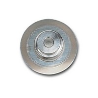
Figure 1a.
4
IMAGE SIDE
OF CODEWHEEL
*Please note that the image side of the codewheel must always be facing the module Side A.
HEDS-51X0 fig 1a
MODULE SIDE B
MODULE SIDE A
Mounting with Module Side A as the Mounting Plane
Mounting a high resolution or three channel encoder
with Module Side A as the mounting plane requires
alignment pins in the motor base. These alignment pins
provide the necessary centering of the module with
respect to the center of the motor shaft. In addition to
centering, the codewheel gap is also important. Please
refer to the respective encoder data sheet for necessary
mounting information.
Mounting with Module Side B as the Mounting Plane,
using Avago Technologies Assembly Tools
Avago Technologies offers centering tools and gap set-
ting tools only for the case when the module is mount-
ed with Side B down. Please refer to the Ordering Infor-
mation Table to choose the correct assembly tools.
Figure 1b.
IMAGE SIDE
OF CODEWHEEL
MODULE SIDE A
MODULE SIDE B
Related parts for HEDS-5140#C13
Image
Part Number
Description
Manufacturer
Datasheet
Request
R

Part Number:
Description:
ENCODER OPTICAL GAP 3CH 500CPR
Manufacturer:
Avago Technologies US Inc.
Datasheet:

Part Number:
Description:
Encoders 2 Channel 256CPR
Manufacturer:
Avago Technologies US Inc.
Datasheet:
Part Number:
Description:
Encoders 2 Channel 150CPR
Manufacturer:
Avago Technologies US Inc.
Datasheet:
Part Number:
Description:
Encoders 2 Channel 120CPR
Manufacturer:
Avago Technologies US Inc.
Datasheet:
Part Number:
Description:
SML ENC MOD 2CH BENT LDS 100 CPR
Manufacturer:
Avago Technologies US Inc.
Datasheet:
Part Number:
Description:
Encoders 2 Channel 400CPR
Manufacturer:
Avago Technologies US Inc.
Datasheet:

Part Number:
Description:
Encoders 2 Channel 180CPR
Manufacturer:
Avago Technologies US Inc.
Datasheet:
Part Number:
Description:
Encoders 2 Channel 400CPR
Manufacturer:
Avago Technologies US Inc.
Datasheet:
Part Number:
Description:
Encoders 2 Channel 150CPR
Manufacturer:
Avago Technologies US Inc.
Datasheet:
Part Number:
Description:
Encoders 2 Channel 150CPR
Manufacturer:
Avago Technologies US Inc.
Datasheet:
Part Number:
Description:
Encoders 2 Channel 150CPR
Manufacturer:
Avago Technologies US Inc.
Datasheet:
Part Number:
Description:
Encoders 2 Channel 150CPR
Manufacturer:
Avago Technologies US Inc.
Datasheet:
Part Number:
Description:
Encoders 2 Channel 360CPR
Manufacturer:
Avago Technologies US Inc.
Datasheet:
Part Number:
Description:
Encoders 2 Channel 150CPR
Manufacturer:
Avago Technologies US Inc.
Datasheet:
Part Number:
Description:
Encoders 2 Channel 400CPR
Manufacturer:
Avago Technologies US Inc.
Datasheet: