PROPER USE GUIDELINES
Cumulative Trauma Disorders can result from the prolonged use of manually powered hand tools. Hand tools are intended for occasional use and low volume
applications. A wide selection of powered application equipment for extended- - use, production operations is available.
1. INTRODUCTION
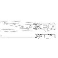
Hand Crimping Tool Frame Assembly 543344--1 is
designed to crimp the ferrule onto the shielding
hardware or cable clamps used with AMPLIMITE
HD--20 connectors. This tool accepts interchangeable
dies which corresponds to the ferrule being crimped.
E2011 Tyco Electronics Corporation, a TE Connectivity Ltd. Company
All Rights Reserved
*Trademark
TE Connectivity, TE connectivity (logo), and TE (logo) are trademarks. Other logos, product and/or Company names may be trademarks of their respective owners.
NOTE
i
Die Holder
Plate
Ratchet
Lower
Die Holder
Dimensions in this instruction sheet are in
millimeters [with inches in brackets]. Figures and
illustrations are for reference only and are not
drawn to scale.
Figure 1
Hand Crimping Tool Frame Assembly
543344- 1 (Used to Crimp Ferrules for
AMPLIMITE* HD- 20 Connectors)
Front of Tool
Flip- - Top
Head
Handles
Latch
TOOLING ASSISTANCE CENTER 1--800--722--1111
PRODUCT INFORMATION 1--800--522--6752
Reasons for reissue of this instruction sheet are
provided in Section 7, REVISION SUMMARY.
2. DESCRIPTION
The tool consists of a flip--top head with a latch, die
holder plate, lower die holder, and handles with a
ratchet. The flip--top head allows easy removal of the
ferrule. The part number of the tool is on the front of
the tool.
This tool is a member of the CERTI--CRIMP* hand
crimping tool family. The ratchet on this tool ensures
full crimping of the product. Once engaged, the
ratchet will not release until the handles have been
FULLY closed.
3. DIE INSERTION AND REMOVAL
3.1. Installation
3.2. Removal
CAUTION
NOTE
1. Close the handles until the ratchet releases.
Allow the handles to open FULLY.
2. Place the moving die in the lower die holder.
Turn the die holding screw enough to hold die in
place. DO NOT tighten the screw.
3. Place the stationary die in the die holder plate.
Turn the die holding screw enough to hold the die
in place. DO NOT tighten the screw.
4. Make sure that the dies and properly aligned,
then close the handles, and tighten the die holding
screws.
1. Close the handles until the ratchet releases.
Allow the handles to open FULLY.
2. Loosen the die holding screws, and remove the
dies.
!
i
The dies bottom before the ratchet releases. This
feature ensures maximum electrical and tensile
performance of the crimp. DO NOT re- - adjust the
ratchet.
Each set of dies consists of an anvil (moving die)
and a crimper (stationary die). Most moving dies
have square corners and the stationary dies have
chamfered corners. Refer to Figure 2. Exceptions
to this feature will be shown on the instruction
sheet packaged with the dies.
(Refer to Figure 2)
(Figure 1)
This controlled document is subject to change.
For latest revision and Regional Customer Service,
visit our website at www.te.com
Instruction Sheet
408- - 9315
11 APR 11
Rev C
1 of 4
LOC B