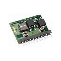
ZY2105G-R1 POWER ONE, ZY2105G-R1 Datasheet

ZY2105G-R1
Specifications of ZY2105G-R1
Available stocks
Related parts for ZY2105G-R1
ZY2105G-R1 Summary of contents
Page 1
Applications Low voltage, high density systems with Intermediate Bus Architectures (IBA) Point-of-load regulators for high performance DSP, FPGA, ASIC, and microprocessor applications Industrial computing, servers, and storage Broadband, networking, optical, and wireless communications systems Active ...
Page 2
... Mercury (Hg), Polybrominated biphenyls (PBB), Polybrominated diphenylethers (PBDE), and Lead (Pb) used anywhere except in solder. 2 Packaging option is used only for ordering and not included in the part number printed on the POL converter label. Example: ZY2105G-R3: A 48-piece tray of RoHS compliant POL converters. Each POL converter is labeled ZY2105G. 2. Absolute Maximum Ratings Stresses in excess of the absolute maximum ratings may cause performance degradation, adversely affect long- term reliability, and cause permanent damage to the POL converter ...
Page 3
Electrical Specifications Specifications apply at the input voltage from 8V to 14V, output load from 0 to 5A, ambient temperature from 0°C to 70°C, output capacitance consisting of 3x22F ceramics and a 47F tantalum, and the CCA=0 unless otherwise ...
Page 4
Protection Specifications Parameter Type Threshold Threshold Accuracy Type Threshold Follows the output voltage setpoint Threshold Accuracy From instant when threshold is exceeded until Delay the turn-off command is generated Type Threshold Follows the output voltage setpoint Threshold Accuracy From ...
Page 5
Feature Specifications Parameter Rising Slew Rate Falling Slew Rate EN Pin Polarity EN High Threshold EN Low Threshold Open Circuit Voltage From EN pin changing state to V Turn-On Delay From EN pin changing state to V Turn-Off Delay ...
Page 6
Signal Specifications Parameter VDD ViL_s ViH_s Vhyst_s Hysteresis of input Schmitt trigger IoL_s LOW level sink current V(SYNC)=0.5V Ipu_s Pull-up current source V(SYNC)=0V Tr_s Maximum allowed rise time 10/90%VDD Cnode_s Freq_s Clock frequency of external SYNC line Tsynq T0 ...
Page 7
Typical Performance Characteristics 5.1 Efficiency Curves Vo=5.0V Vo=3.3V 60 Vo=1.8V Vo=1. Output Current, A Figure 1. Efficiency vs. Load. Vin=9. ...
Page 8
Turn-On Characteristics Figure 5. Tracking Turn-On. Vin=12V, Ch1 – V1, Ch2 – V2, Ch3 – V3 5.3 Turn-Off Characteristics Figure 6. Tracking Turn-Off Vin=12V, Ch1 – V1, Ch2 – V2, Ch3 – V3 ZD-01967 Rev. B1.2 ZY2105 5A No-Bus ...
Page 9
Figure 9. Vin=12V, Vout=1V. CCA=0 5.5 Thermal Derating Curve 5 4.5 4 3.5 3 2.5 2 1.5 0LFM 100LFM Figure 11. Thermal Derating Curves. Vin=12V, Vout=5V ZD-01967 Rev. B1.2 ZY2105 5A No-Bus POL Data Sheet 8V to ...
Page 10
Typical Application IBV ENABLE SYNC TRIM PGOOD MARGIN EN POL1 CCA IM Figure 12. Complete Schematic of Application with Three Independent Outputs. Intermediate Bus Voltage is from 8V to 14V. In this application three POL converters are configured to ...
Page 11
Pin Assignments and Description Pin Pin Pin Buffer Name Number Type Type OK 8 I/O PU SYNC 9 I/O PU PGOOD 6 I CCA MARGIN ...
Page 12
Pin and Feature Description 8.1 OK, Fault Status The open drain input/output with the internal pull-up resistor. The POL converter pulls its OK pin low fault occurs. Pulling low the OK input by an external circuitry turns ...
Page 13
R is the value of the trim resistor in kΩ and TRIM ΔV% is the absolute value of desired margining expressed in percents of the nominal output voltage. During normal operation the resistors are removed from the circuit by ...
Page 14
Mechanical Drawings Tolerances: Notes: 1. NUCLEAR AND MEDICAL APPLICATIONS - Power-One products are not designed, intended for use in, or authorized for use as critical components in life support systems, equipment used in hazardous environments, or nuclear control systems ...


