DDTA114YKA-7-F Diodes Inc, DDTA114YKA-7-F Datasheet

TRANS PNP 200MW R1/R2 SC59-3

DDTA114YKA-7-F

Manufacturer Part Number
DDTA114YKA-7-F
Description
TRANS PNP 200MW R1/R2 SC59-3
Manufacturer
Diodes Inc
Datasheet

Specifications of DDTA114YKA-7-F

Transistor Type
PNP - Pre-Biased
Current - Collector (ic) (max)
70mA
Voltage - Collector Emitter Breakdown (max)
50V
Resistor - Base (r1) (ohms)
10K
Resistor - Emitter Base (r2) (ohms)
47K
Dc Current Gain (hfe) (min) @ Ic, Vce
68 @ 10mA, 5V
Vce Saturation (max) @ Ib, Ic
300mV @ 250µA, 5mA
Frequency - Transition
250MHz
Power - Max
200mW
Mounting Type
Surface Mount
Package / Case
SC-59-3, SMT3, SOT-346, TO-236
Lead Free Status / RoHS Status
Lead free / RoHS Compliant

Available stocks

Company
Part Number
Manufacturer
Quantity
Price
Part Number:
DDTA114YKA-7-F
Manufacturer:
DIODES
Quantity:
18 000
Mechanical Data
Maximum Ratings
Features
Supply Voltage, (3) to (2)
Input Voltage, (1) to (2)
Output Current
Notes:
DS30342 Rev. 7 - 2
DDTA114WKA
DDTA144WKA
DDTA113ZKA
DDTA123YKA
DDTA143XKA
DDTA143FKA
DDTA143ZKA
DDTA114YKA
DDTA124XKA
DDTA144VKA
DDTA123JKA
Epitaxial Planar Die Construction
Complementary NPN Types Available (DDTC)
Built-In Biasing Resistors, R1≠R2
Lead Free/RoHS Compliant (Note 1)
"Green" Device, Note 2 and 3
Case: SC-59
Case material: Molded Plastic, "Green" Molding
Compound, Note 3. UL Flammability Classification
Rating 94V-0
Moisture Sensitivity: Level 1 per J-STD-020C
Terminals: Solderable per MIL-STD-202, Method 208
Lead Free Plating (Matte Tin Finish annealed over
Copper leadframe).
Terminal Connections: See Diagram
Marking Information: See Table Below & Page 4
Ordering Information: See Page 4
Weight: 0.008 grams (approximate)
P/N
1. No purposefully added lead.
2. Diodes Inc.'s "Green" policy can be found on our website at http://www.diodes.com/products/lead_free/index.php.
3. Product manufactured with Date Code 0627 (week 27, 2006) and newer are built with Green Molding Compound. Product manufactured prior to Date
Code 0627 are built with Non-Green Molding Compound and may contain Halogens or Sb2O3 Fire Retardants.
R1 (NOM) R2 (NOM)
2.2KΩ
2.2KΩ
4.7KΩ
4.7KΩ
4.7KΩ
10KΩ
10KΩ
22KΩ
47KΩ
47KΩ
1KΩ
Characteristic
@T
4.7KΩ
A
10KΩ
10KΩ
47KΩ
10KΩ
22KΩ
47KΩ
47KΩ
47KΩ
10KΩ
22KΩ
= 25°C unless otherwise specified
Type Code
P02
P05
P06
P09
P10
P11
P14
P15
P18
P21
P22
DDTA113ZKA
DDTA113ZKA
DDTA123YKA
DDTA123JKA
DDTA143XKA
DDTA143FKA
DDTA143ZKA
DDTA114YKA
DDTA114WKA
DDTA124XKA
DDTA144VKA
DDTA144WKA
DDTA123YKA
DDTA123JKA
DDTA143XKA
DDTA143FKA
DDTA143ZKA
DDTA114YKA
DDTA114WKA
DDTA124XKA
DDTA144VKA
DDTA144WKA
PNP PRE-BIASED SMALL SIGNAL SURFACE MOUNT TRANSISTOR
www.diodes.com
K
J
1 of 4
Schematic and Pin Configuration
Symbol
A
G
H
V
V
I
CC
O
IN
IN
D
1
DDTA
B
R1
OUT
3
C
B
R2
C
L
GND(+)
2
E
(R1≠R2 SERIES)
+10 to -30
+10 to -40
+15 to -40
+10 to -40
+5 to -10
+5 to -12
+5 to -12
+7 to -20
+6 to -30
+5 to -30
+6 to -40
Value
-100
-100
-100
-100
-100
-100
-100
-50
-70
-50
-30
-30
M
IN
Equivalent Inverter Circuit
DDTA (R1≠R2 SERIES) KA
B
Dim
All Dimensions in mm
G
M
A
B
C
D
H
K
α
J
L
1
SC-59
0.013
GND (+)
0.35
1.50
2.70
2.90
1.00
0.35
0.10
Min
© Diodes Incorporated
E
Unit
mA
V
V
0.95
1.90
3
KA
Max
0.50
1.70
3.00
3.10
0.10
1.30
0.55
0.20
C
OUT

Related parts for DDTA114YKA-7-F

DDTA114YKA-7-F Summary of contents

Page 1

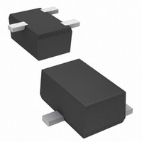
... Schematic and Pin Configuration Symbol V CC DDTA113ZKA DDTA123YKA DDTA123JKA DDTA143XKA DDTA143FKA DDTA143ZKA V IN DDTA114YKA DDTA114WKA DDTA124XKA DDTA144VKA DDTA144WKA DDTA113ZKA DDTA123YKA DDTA123JKA DDTA143XKA DDTA143FKA DDTA143ZKA I O DDTA114YKA DDTA114WKA DDTA124XKA DDTA144VKA DDTA144WKA www.diodes.com (R1≠R2 SERIES) SC-59 Dim Min C A 0.35 B 1.50 C 2.70 D 0. ...

Page 2

... I = -1mA -0.3V -2mA -0.3V -2mA -0.3V -2mA -0.3V -2mA -5mA/-0.25mA DDTA123JKA -5mA/-0.25mA DDTA143ZKA -5mA/-0.25mA DDTA114YKA -10mA/-0.5mA All Others -5V I μ -50V ⎯ -5V -10mA O O ⎯ % ⎯ -10V 5mA MHz f = 100MHz DDTA (R1≠R2 SERIES) KA © Diodes Incorporated ...

Page 3

... 0 www.diodes.com ° -25 C ° ° COLLECTOR CURRENT (mA) C Fig vs. I CE(SAT 1MHz REVERSE BIAS VOLTAGE (V) R Fig. 4 Output Capacitance V = 0.2V O -25° ° 25° COLLECTOR CURRENT (mA) C Fig. 6 Input Voltage vs. Collector Current DDTA (R1≠R2 SERIES) KA © Diodes Incorporated ...

Page 4

... Ordering Information (Note 3 & 5) Device DDTA113ZKA-7-F DDTA123YKA-7-F DDTA123JKA-7-F DDTA143XKA-7-F DDTA143FKA-7-F DDTA143ZKA-7-F DDTA114YKA-7-F DDTA114WKA-7-F DDTA124XKA-7-F DDTA144VKA-7-F DDTA144WKA-7-F Notes: 5. For packaging details our website at http://www.diodes.com/datasheets/ap02007.pdf. Marking Information PXX Date Code Key Year 2002 2003 2004 Code N P Month Jan Feb Mar Code ...

Related keywords